How to Use ADXL335: Examples, Pinouts, and Specs
Introduction
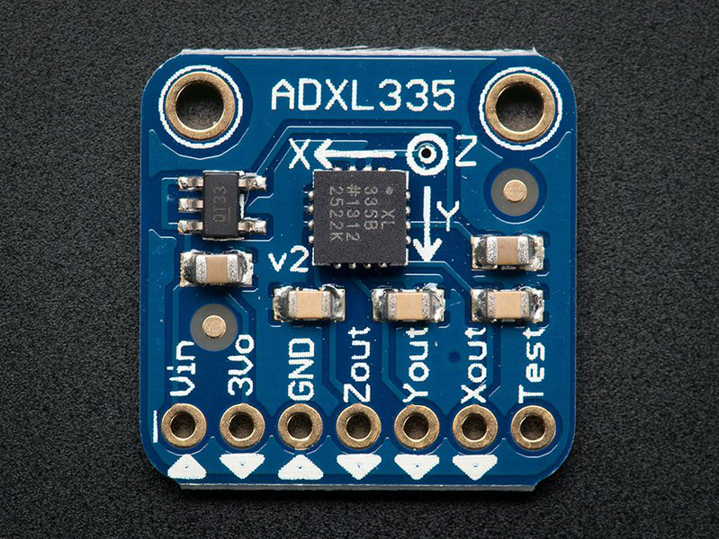
The ADXL335 is a small, thin, low-power, 3-axis accelerometer designed to measure acceleration in the X, Y, and Z axes. It provides analog output voltages proportional to the detected acceleration, making it an ideal choice for applications requiring motion sensing, tilt detection, and vibration monitoring. Its compact size and low power consumption make it suitable for portable and battery-powered devices.
Explore Projects Built with ADXL335
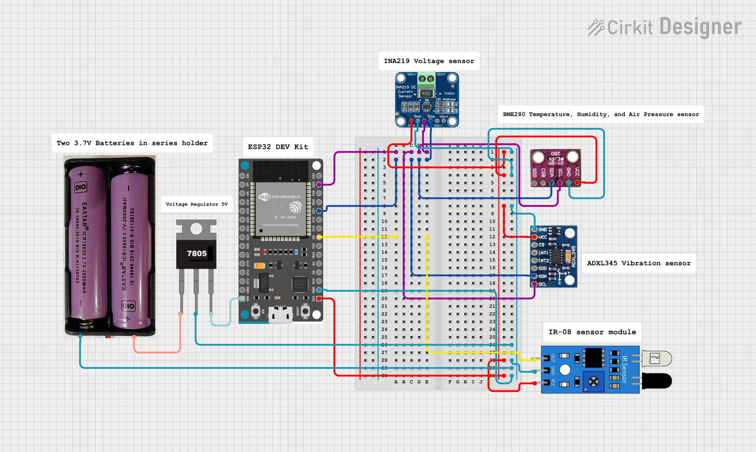

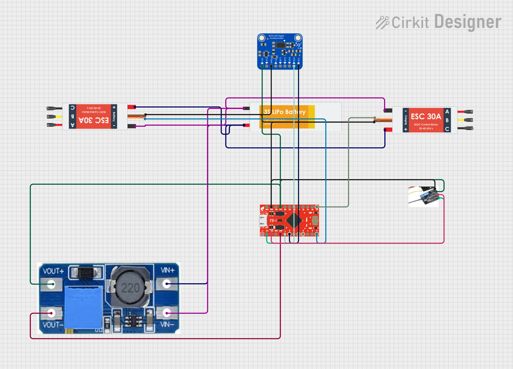
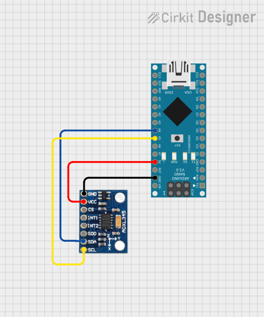
Explore Projects Built with ADXL335
Common Applications
- Motion sensing in mobile devices
- Tilt detection in robotics and gaming controllers
- Vibration monitoring in industrial equipment
- Orientation sensing in wearable devices
- Impact detection in automotive systems
Technical Specifications
The ADXL335 is a versatile accelerometer with the following key specifications:
| Parameter | Value |
|---|---|
| Supply Voltage (VCC) | 1.8V to 3.6V |
| Typical Operating Voltage | 3.3V |
| Power Consumption | 350 µA (typical) |
| Measurement Range | ±3 g |
| Sensitivity | 300 mV/g (at 3.3V supply) |
| Bandwidth | Selectable via external capacitors |
| Output Type | Analog |
| Operating Temperature Range | -40°C to +85°C |
| Dimensions | 4 mm × 4 mm × 1.45 mm (LFCSP) |
Pin Configuration and Descriptions
The ADXL335 has a 5-pin configuration, as detailed below:
| Pin Name | Pin Number | Description |
|---|---|---|
| VCC | 1 | Power supply input (1.8V to 3.6V) |
| GND | 2 | Ground |
| XOUT | 3 | Analog output voltage proportional to X-axis acceleration |
| YOUT | 4 | Analog output voltage proportional to Y-axis acceleration |
| ZOUT | 5 | Analog output voltage proportional to Z-axis acceleration |
Usage Instructions
How to Use the ADXL335 in a Circuit
- Power Supply: Connect the VCC pin to a 3.3V power source and the GND pin to ground.
- Output Connections: Connect the XOUT, YOUT, and ZOUT pins to the analog input pins of a microcontroller or ADC (Analog-to-Digital Converter).
- Bandwidth Selection: Use external capacitors on the XOUT, YOUT, and ZOUT pins to set the bandwidth. The capacitor value determines the cutoff frequency:
- Bandwidth (Hz) = 1 / (2π × R × C), where R = 32 kΩ (internal resistor).
- For example, a 0.1 µF capacitor results in a bandwidth of approximately 50 Hz.
- Signal Conditioning: Ensure the analog signals are within the input range of the microcontroller or ADC.
Important Considerations
- Noise Filtering: Use appropriate capacitors to filter high-frequency noise.
- Alignment: Mount the ADXL335 on a stable surface to ensure accurate readings.
- Calibration: Perform calibration to account for offsets and ensure precise measurements.
- Power Supply Stability: Use a decoupling capacitor (e.g., 0.1 µF) near the VCC pin to stabilize the power supply.
Example: Connecting ADXL335 to Arduino UNO
Below is an example of how to connect and read data from the ADXL335 using an Arduino UNO:
Circuit Connections
- Connect VCC to the 3.3V pin on the Arduino.
- Connect GND to the GND pin on the Arduino.
- Connect XOUT, YOUT, and ZOUT to Arduino analog pins A0, A1, and A2, respectively.
Arduino Code
// Define the analog pins connected to the ADXL335 outputs
const int xPin = A0; // X-axis output
const int yPin = A1; // Y-axis output
const int zPin = A2; // Z-axis output

void setup() {
  // Initialize serial communication for debugging
  Serial.begin(9600);
}

void loop() {
  // Read analog values from the ADXL335
  int xValue = analogRead(xPin); // Read X-axis value
  int yValue = analogRead(yPin); // Read Y-axis value
  int zValue = analogRead(zPin); // Read Z-axis value

  // Convert the raw analog values to voltage (assuming 3.3V reference)
  float xVoltage = xValue * (3.3 / 1023.0);
  float yVoltage = yValue * (3.3 / 1023.0);
  float zVoltage = zValue * (3.3 / 1023.0);

  // Print the voltage values to the Serial Monitor
  Serial.print("X Voltage: ");
  Serial.print(xVoltage);
  Serial.print(" V, Y Voltage: ");
  Serial.print(yVoltage);
  Serial.print(" V, Z Voltage: ");
  Serial.print(zVoltage);
  Serial.println(" V");

  // Add a small delay for stability
  delay(500);
}
Troubleshooting and FAQs
Common Issues and Solutions
No Output Signal:
- Cause: Incorrect power supply or loose connections.
- Solution: Verify that VCC is connected to a stable 3.3V source and all connections are secure.
Inconsistent Readings:
- Cause: Excessive noise or improper capacitor selection.
- Solution: Use appropriate capacitors to filter noise and stabilize the output.
Incorrect Voltage Levels:
- Cause: Mismatched reference voltage on the microcontroller.
- Solution: Ensure the microcontroller's ADC reference voltage matches the ADXL335's supply voltage.
High Power Consumption:
- Cause: Faulty wiring or excessive load on the output pins.
- Solution: Check for short circuits and ensure the output pins are connected to high-impedance inputs.
FAQs
Q1: Can the ADXL335 measure static acceleration (e.g., gravity)?
Yes, the ADXL335 can measure static acceleration, such as gravity, making it suitable for tilt and orientation sensing.
Q2: How do I calculate the acceleration from the output voltage?
Acceleration (g) = (Output Voltage - Zero-g Voltage) / Sensitivity.
For example, at 3.3V supply, the zero-g voltage is approximately 1.65V, and the sensitivity is 300 mV/g.
Q3: Can I use the ADXL335 with a 5V microcontroller?
Yes, but you must use a voltage divider or level shifter to ensure the output voltages are within the microcontroller's ADC input range.
Q4: What is the maximum bandwidth of the ADXL335?
The maximum bandwidth is 1600 Hz for the X and Y axes and 550 Hz for the Z axis, determined by the external capacitors.
By following this documentation, you can effectively integrate the ADXL335 into your projects for reliable motion and tilt sensing.