Cirkit Designer
Your all-in-one circuit design IDE
Home /
Component Documentation
How to Use DS3231 Real Time Clock: Examples, Pinouts, and Specs
Introduction
The DS3231 Real Time Clock (RTC) module is a low-cost, extremely accurate I2C real-time clock with an integrated temperature-compensated crystal oscillator (TCXO) and crystal. The module maintains seconds, minutes, hours, day, date, month, and year information, with automatic leap year compensation valid up to 2100. It is commonly used in electronics projects where time tracking is essential, such as data loggers, clocks, and access systems.
Explore Projects Built with DS3231 Real Time Clock
Arduino Nano Based Real-Time Clock Display with TM1637

This circuit features an Arduino Nano interfacing with a DS3231 Real-Time Clock for timekeeping and a TM1637 display module for visual output. The Arduino facilitates I2C communication with the RTC and controls the display using digital IO, serving as the central processing unit for a digital clock or timer application.
Dual RTC DS3231 Synchronization with Glyph C3 Microcontroller

This circuit integrates two RTC DS3231 real-time clock modules with a Glyph C3 microcontroller. The RTC modules are connected to the microcontroller via I2C communication protocol, using the SCL and SDA lines for clock and data respectively. Both RTC modules and the microcontroller share a common power supply (3V3) and ground (GND), indicating that they operate at the same voltage level.
Arduino-Based Real-Time Clock with DS1307 RTC
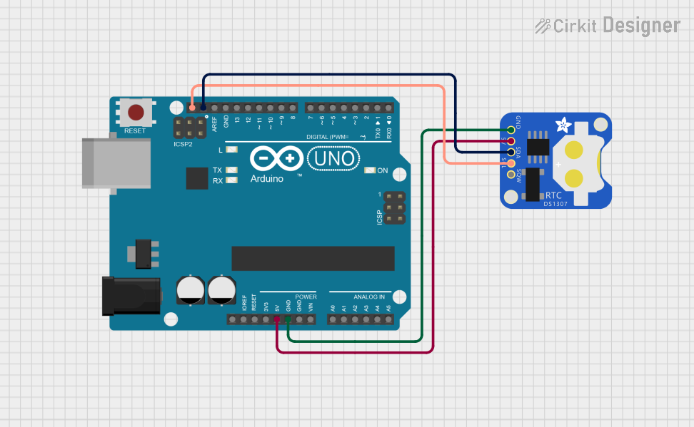
This circuit integrates an Arduino UNO with a DS1307 Real-Time Clock (RTC) module to keep track of the current date and time. The Arduino communicates with the RTC via I2C (SDA and SCL lines) and displays the time on the serial monitor, ensuring accurate timekeeping even during power outages.
I2C RTC Clock with Pushbutton Controls and LCD Display
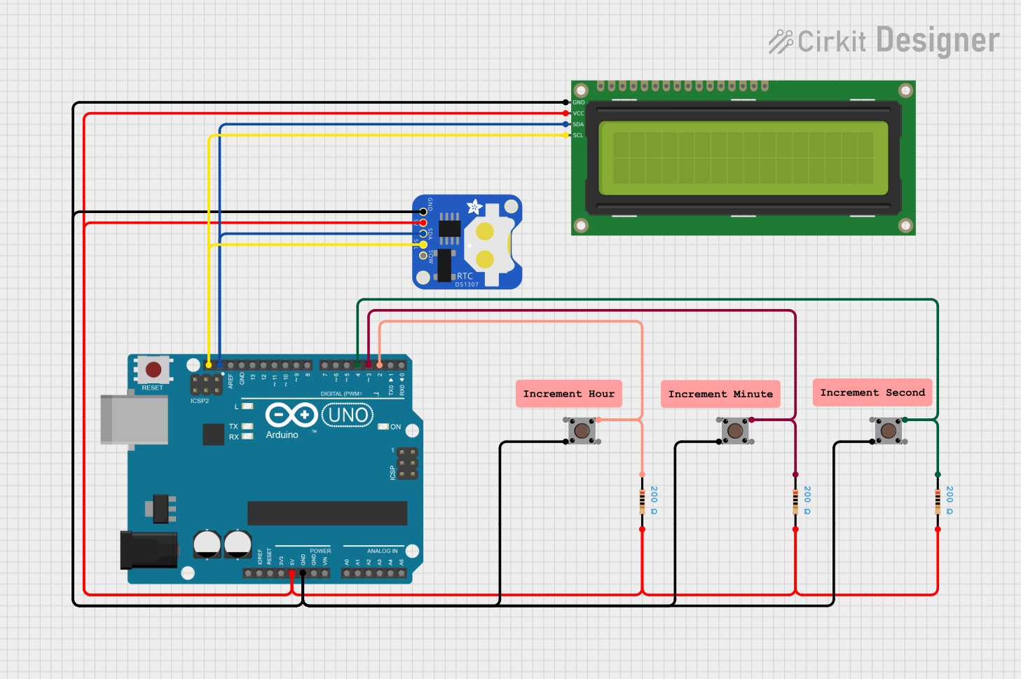
This circuit is a digital clock that utilizes a DS1307 real-time clock (RTC) module to keep track of time and a 16x2 I2C LCD to display the current date and time. It features three pushbuttons for adjusting the hours, minutes, and seconds, which are connected to an Arduino UNO microcontroller that handles the logic and updates the display accordingly.
Explore Projects Built with DS3231 Real Time Clock
Arduino Nano Based Real-Time Clock Display with TM1637
This circuit features an Arduino Nano interfacing with a DS3231 Real-Time Clock for timekeeping and a TM1637 display module for visual output. The Arduino facilitates I2C communication with the RTC and controls the display using digital IO, serving as the central processing unit for a digital clock or timer application.
Dual RTC DS3231 Synchronization with Glyph C3 Microcontroller
This circuit integrates two RTC DS3231 real-time clock modules with a Glyph C3 microcontroller. The RTC modules are connected to the microcontroller via I2C communication protocol, using the SCL and SDA lines for clock and data respectively. Both RTC modules and the microcontroller share a common power supply (3V3) and ground (GND), indicating that they operate at the same voltage level.
Arduino-Based Real-Time Clock with DS1307 RTC
This circuit integrates an Arduino UNO with a DS1307 Real-Time Clock (RTC) module to keep track of the current date and time. The Arduino communicates with the RTC via I2C (SDA and SCL lines) and displays the time on the serial monitor, ensuring accurate timekeeping even during power outages.
I2C RTC Clock with Pushbutton Controls and LCD Display
This circuit is a digital clock that utilizes a DS1307 real-time clock (RTC) module to keep track of time and a 16x2 I2C LCD to display the current date and time. It features three pushbuttons for adjusting the hours, minutes, and seconds, which are connected to an Arduino UNO microcontroller that handles the logic and updates the display accordingly.
Common Applications and Use Cases
- Timekeeping for embedded systems
- Data logging with time stamps
- Clocks and watches
- Access control systems
- IoT devices with scheduled tasks
Technical Specifications
Key Technical Details
- Time Accuracy: ±2ppm from 0°C to +40°C
- Battery Backup: Yes (typically a 3V CR2032 coin cell)
- Operating Voltage: 2.3V to 5.5V
- Operating Temperature: -40°C to +85°C
- Interface: I2C Serial
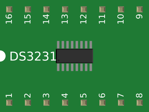
Pin Configuration and Descriptions
| Pin Number | Pin Name | Description |
|---|---|---|
| 1 | VCC | Power supply (2.3V to 5.5V) |
| 2 | GND | Ground |
| 3 | SDA | Serial Data Line for I2C communication |
| 4 | SCL | Serial Clock Line for I2C communication |
| 5 | SQW | Square Wave/Interrupt Output |
| 6 | 32K | 32kHz Output |
| 7 | RST | Reset Input (Active Low) |
Usage Instructions
How to Use the Component in a Circuit
- Power Connections: Connect VCC to a 2.3V to 5.5V power supply and GND to the ground of your system.
- I2C Communication: Connect SDA and SCL to your microcontroller's I2C data and clock lines, respectively. Use pull-up resistors if your microcontroller does not have built-in pull-ups on these lines.
- Square Wave/Interrupt Output: The SQW pin can be configured to output a square wave signal or act as an interrupt output. This is optional and based on your application needs.
- 32kHz Output: The 32K pin outputs a 32kHz square wave that can be used to drive other circuits or microcontroller peripherals.
- Reset Input: The RST pin is an optional reset input that can be used to reset the RTC module.
Important Considerations and Best Practices
- Ensure that the power supply is within the specified range to avoid damaging the module.
- The battery backup allows the DS3231 to continue keeping time when the main power is lost. Make sure to install a 3V coin cell battery if this feature is required.
- Use proper decoupling capacitors close to the module's power pins to minimize power supply noise.
- The I2C address of the DS3231 is fixed at 0x68 and cannot be changed.
Troubleshooting and FAQs
Common Issues Users Might Face
- Incorrect Time: Ensure the battery is installed correctly and has sufficient voltage. Check the I2C communication and verify the correct initialization of the RTC in your code.
- No Communication: Check the wiring of SDA and SCL lines, including pull-up resistors. Verify that no other device on the I2C bus has a conflicting address.
Solutions and Tips for Troubleshooting
- If the time drifts significantly, consider checking the temperature where the DS3231 is operating, as extreme temperatures can affect the accuracy.
- For communication issues, use an I2C scanner sketch to ensure the DS3231 is detected on the bus.
Example Code for Arduino UNO
#include <Wire.h>
#include <RTClib.h>

RTC_DS3231 rtc;

void setup() {
  Serial.begin(9600);
  if (!rtc.begin()) {
    Serial.println("Couldn't find RTC");
    while (1);
  }

  if (rtc.lostPower()) {
    Serial.println("RTC lost power, let's set the time!");
    // The following line sets the RTC to the date & time this sketch was compiled
    rtc.adjust(DateTime(F(__DATE__), F(__TIME__)));
  }
}

void loop() {
  DateTime now = rtc.now();

  Serial.print(now.year(), DEC);
  Serial.print('/');
  Serial.print(now.month(), DEC);
  Serial.print('/');
  Serial.print(now.day(), DEC);
  Serial.print(" ");
  Serial.print(now.hour(), DEC);
  Serial.print(':');
  Serial.print(now.minute(), DEC);
  Serial.print(':');
  Serial.print(now.second(), DEC);
  Serial.println();

  delay(1000);
}
Note: This example uses the RTClib library, which can be installed via the Arduino Library Manager. The code initializes the DS3231 RTC and prints the current time to the Serial Monitor every second. If the RTC has lost power, it will set the time to the time the sketch was compiled.