How to Use HGLRC M100 Mini GPS: Examples, Pinouts, and Specs
Introduction
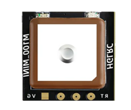
The HGLRC M100 Mini GPS is a compact and lightweight GPS module designed for drones, RC vehicles, and other applications requiring precise positioning and navigation data. Manufactured by HGLRC Company, this module is ideal for projects where size, weight, and accuracy are critical. It supports multiple satellite systems, including GPS, GLONASS, and Galileo, ensuring reliable performance in various environments.
Explore Projects Built with HGLRC M100 Mini GPS


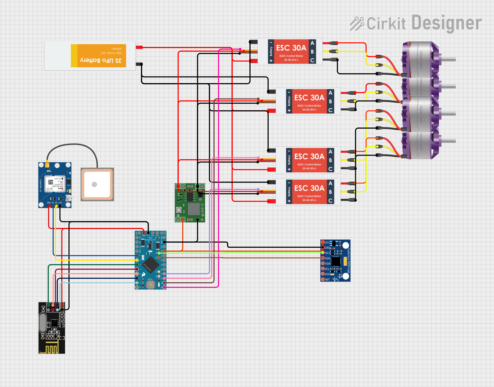
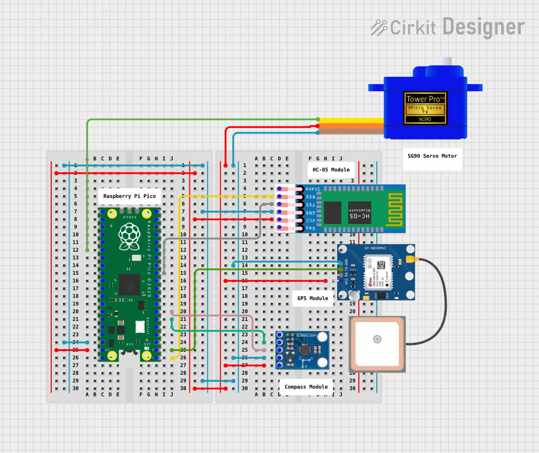
Explore Projects Built with HGLRC M100 Mini GPS
Common Applications
- GPS-enabled drones for navigation and return-to-home functionality
- RC vehicles for location tracking and telemetry
- Robotics projects requiring real-time positioning
- IoT devices for geolocation services
- DIY electronics projects involving GPS data logging
Technical Specifications
The HGLRC M100 Mini GPS module is engineered for high performance in a small form factor. Below are its key technical details:
| Parameter | Specification |
|---|---|
| Dimensions | 22mm x 20mm x 6mm |
| Weight | 5g |
| Input Voltage | 3.3V - 5.0V |
| Operating Current | 40mA (typical) |
| Communication Protocol | UART (default baud rate: 9600 bps) |
| Satellite Systems | GPS, GLONASS, Galileo |
| Positioning Accuracy | ±1.5m (open sky) |
| Cold Start Time | < 30 seconds |
| Hot Start Time | < 1 second |
| Operating Temperature | -40°C to +85°C |
Pin Configuration and Descriptions
The HGLRC M100 Mini GPS module has a 4-pin interface for easy integration into your projects. Below is the pinout:
| Pin | Name | Description |
|---|---|---|
| 1 | VCC | Power input (3.3V - 5.0V) |
| 2 | GND | Ground connection |
| 3 | TX | UART Transmit (GPS data output) |
| 4 | RX | UART Receive (for configuration, if supported) |
Usage Instructions
How to Use the HGLRC M100 Mini GPS in a Circuit
- Power the Module: Connect the
VCCpin to a 3.3V or 5.0V power source and theGNDpin to the ground of your circuit. - Connect UART: Use the
TXpin to send GPS data to your microcontroller or computer. Optionally, connect theRXpin if you need to send configuration commands to the module. - Antenna Placement: Ensure the module's built-in antenna has a clear view of the sky for optimal satellite reception.
- Data Parsing: The module outputs NMEA sentences (e.g.,
$GPGGA,$GPRMC) via UART. Use a microcontroller or software to parse this data for latitude, longitude, altitude, and other information.
Important Considerations and Best Practices
- Power Supply: Ensure a stable power supply within the specified voltage range to avoid damage or unreliable operation.
- Antenna Orientation: Place the module with the antenna facing upward and away from obstructions or sources of interference.
- UART Configuration: The default baud rate is 9600 bps. Ensure your microcontroller or computer is configured to match this rate.
- Cold Start vs. Hot Start: After powering on, the module may take up to 30 seconds to acquire a GPS fix (cold start). Subsequent starts (hot start) are much faster if the module retains satellite data.
Example: Connecting to an Arduino UNO
Below is an example of how to connect the HGLRC M100 Mini GPS to an Arduino UNO and read GPS data:
Wiring Diagram
| HGLRC M100 Pin | Arduino UNO Pin |
|---|---|
| VCC | 5V |
| GND | GND |
| TX | RX (Pin 0) |
| RX | TX (Pin 1) |
Arduino Code
#include <SoftwareSerial.h>

// Define RX and TX pins for SoftwareSerial
SoftwareSerial gpsSerial(4, 3); // RX = Pin 4, TX = Pin 3

void setup() {
  Serial.begin(9600); // Initialize Serial Monitor
  gpsSerial.begin(9600); // Initialize GPS module communication

  Serial.println("HGLRC M100 Mini GPS Test");
}

void loop() {
  // Check if data is available from the GPS module
  while (gpsSerial.available()) {
    char gpsData = gpsSerial.read(); // Read one character at a time
    Serial.print(gpsData); // Output GPS data to Serial Monitor
  }
}
Notes:
- Use
SoftwareSerialto avoid conflicts with the Arduino's hardware UART (pins 0 and 1). - Ensure the GPS module has a clear view of the sky for accurate data.
Troubleshooting and FAQs
Common Issues and Solutions
No GPS Fix (No Satellite Lock):
- Cause: Obstructed view of the sky or interference.
- Solution: Move the module to an open area with a clear view of the sky. Avoid placing it near metal objects or electronic devices that may cause interference.
No Data Output:
- Cause: Incorrect wiring or UART configuration.
- Solution: Double-check the connections and ensure the baud rate is set to 9600 bps.
Unstable Positioning Data:
- Cause: Weak satellite signal or unstable power supply.
- Solution: Ensure a stable power source and verify the antenna placement.
Module Overheating:
- Cause: Operating outside the specified voltage range.
- Solution: Use a regulated power supply within the 3.3V - 5.0V range.
FAQs
Q: Can the HGLRC M100 Mini GPS work indoors?
A: The module is designed for outdoor use. While it may work near windows, satellite reception is significantly reduced indoors.
Q: How do I change the baud rate of the module?
A: The baud rate can be changed using specific configuration commands sent via the RX pin. Refer to the manufacturer's documentation for details.
Q: What is the maximum altitude the module can operate at?
A: The module is designed to operate up to 18,000 meters (59,055 feet) above sea level.
Q: Can I use this module with a Raspberry Pi?
A: Yes, the module can be connected to a Raspberry Pi via its UART interface. Use the GPIO pins for communication and ensure the baud rate matches.
By following this documentation, you can effectively integrate the HGLRC M100 Mini GPS into your projects and troubleshoot common issues.