Cirkit Designer Logo
Cirkit Designer
Your all-in-one circuit design IDE
Home / 
Component Documentation

How to Use SparkFun Spectral Sensor Breakout - AS7262 Visible (Qwiic): Examples, Pinouts, and Specs

Image of SparkFun Spectral Sensor Breakout - AS7262 Visible (Qwiic)
Cirkit Designer LogoDesign with SparkFun Spectral Sensor Breakout - AS7262 Visible (Qwiic) in Cirkit Designer

Introduction

The SparkFun Spectral Sensor Breakout is a compact and versatile board equipped with the AS7262 sensor that allows for precise detection and quantification of light intensity across six different wavelengths in the visible spectrum. This sensor is particularly useful in applications such as color sensing, light analysis, and environmental monitoring. With its Qwiic connect system, it can be easily integrated into a project without the need for soldering, making it accessible for hobbyists and professionals alike.

Explore Projects Built with SparkFun Spectral Sensor Breakout - AS7262 Visible (Qwiic)

Use Cirkit Designer to design, explore, and prototype these projects online. Some projects support real-time simulation. Click "Open Project" to start designing instantly!
Arduino UNO and AS7262 Color Change Detection System with Bluetooth and OLED Display
Image of CAR project: A project utilizing SparkFun Spectral Sensor Breakout - AS7262 Visible (Qwiic) in a practical application
This circuit is designed to detect color changes in a solution using a spectral sensor, time the change, provide a sound cue via a piezo buzzer, and send the timing data to a computer via a Bluetooth module. The Arduino UNO microcontroller coordinates the sensor readings, timing, and communication, while an OLED display and NeoPixel ring provide visual feedback.
Cirkit Designer LogoOpen Project in Cirkit Designer
STM32F103C8T6-Based Spectral Sensor with ST7735S Display and Pushbutton Control
Image of ColorSensor: A project utilizing SparkFun Spectral Sensor Breakout - AS7262 Visible (Qwiic) in a practical application
This circuit features an STM32F103C8T6 microcontroller interfaced with a China ST7735S 160x128 display and two spectral sensors (Adafruit AS7262 and AS7261). It also includes two pushbuttons for user input, with the microcontroller managing the display and sensor data processing.
Cirkit Designer LogoOpen Project in Cirkit Designer
Battery-Powered Arduino Nano Spectroscopy Sensor
Image of NIRS: A project utilizing SparkFun Spectral Sensor Breakout - AS7262 Visible (Qwiic) in a practical application
This circuit consists of an Arduino Nano microcontroller connected to a SparkFun Triad Spectroscopy Sensor for spectral analysis. The Arduino is powered by a 4 x AAA battery pack and communicates with the sensor via I2C protocol, with additional connections for reset and interrupt signals.
Cirkit Designer LogoOpen Project in Cirkit Designer
Wi-Fi Enabled UV Monitoring System with OLED Display
Image of UV_DETECTOR_BREADBOARD: A project utilizing SparkFun Spectral Sensor Breakout - AS7262 Visible (Qwiic) in a practical application
This circuit features a PicoW microcontroller interfacing with a 0.96" OLED display, an ML8511 UV sensor, and a blue LED. The PicoW reads UV sensor data and can display information on the OLED while controlling the LED for visual feedback.
Cirkit Designer LogoOpen Project in Cirkit Designer

Explore Projects Built with SparkFun Spectral Sensor Breakout - AS7262 Visible (Qwiic)

Use Cirkit Designer to design, explore, and prototype these projects online. Some projects support real-time simulation. Click "Open Project" to start designing instantly!
Image of CAR project: A project utilizing SparkFun Spectral Sensor Breakout - AS7262 Visible (Qwiic) in a practical application
Arduino UNO and AS7262 Color Change Detection System with Bluetooth and OLED Display
This circuit is designed to detect color changes in a solution using a spectral sensor, time the change, provide a sound cue via a piezo buzzer, and send the timing data to a computer via a Bluetooth module. The Arduino UNO microcontroller coordinates the sensor readings, timing, and communication, while an OLED display and NeoPixel ring provide visual feedback.
Cirkit Designer LogoOpen Project in Cirkit Designer
Image of ColorSensor: A project utilizing SparkFun Spectral Sensor Breakout - AS7262 Visible (Qwiic) in a practical application
STM32F103C8T6-Based Spectral Sensor with ST7735S Display and Pushbutton Control
This circuit features an STM32F103C8T6 microcontroller interfaced with a China ST7735S 160x128 display and two spectral sensors (Adafruit AS7262 and AS7261). It also includes two pushbuttons for user input, with the microcontroller managing the display and sensor data processing.
Cirkit Designer LogoOpen Project in Cirkit Designer
Image of NIRS: A project utilizing SparkFun Spectral Sensor Breakout - AS7262 Visible (Qwiic) in a practical application
Battery-Powered Arduino Nano Spectroscopy Sensor
This circuit consists of an Arduino Nano microcontroller connected to a SparkFun Triad Spectroscopy Sensor for spectral analysis. The Arduino is powered by a 4 x AAA battery pack and communicates with the sensor via I2C protocol, with additional connections for reset and interrupt signals.
Cirkit Designer LogoOpen Project in Cirkit Designer
Image of UV_DETECTOR_BREADBOARD: A project utilizing SparkFun Spectral Sensor Breakout - AS7262 Visible (Qwiic) in a practical application
Wi-Fi Enabled UV Monitoring System with OLED Display
This circuit features a PicoW microcontroller interfacing with a 0.96" OLED display, an ML8511 UV sensor, and a blue LED. The PicoW reads UV sensor data and can display information on the OLED while controlling the LED for visual feedback.
Cirkit Designer LogoOpen Project in Cirkit Designer

Technical Specifications

Key Technical Details

  • Spectral Range: 450nm to 650nm (six channels)
  • Resolution: 16-bit digital output per channel
  • Interface: I2C (default), UART (optional)
  • Operating Voltage: 3.3V (5V tolerant)
  • Current Consumption: 5mA (typical)
  • Field of View: 20 degrees
  • Integration Time: 2.8ms to 714ms
  • Operating Temperature: -40°C to 85°C

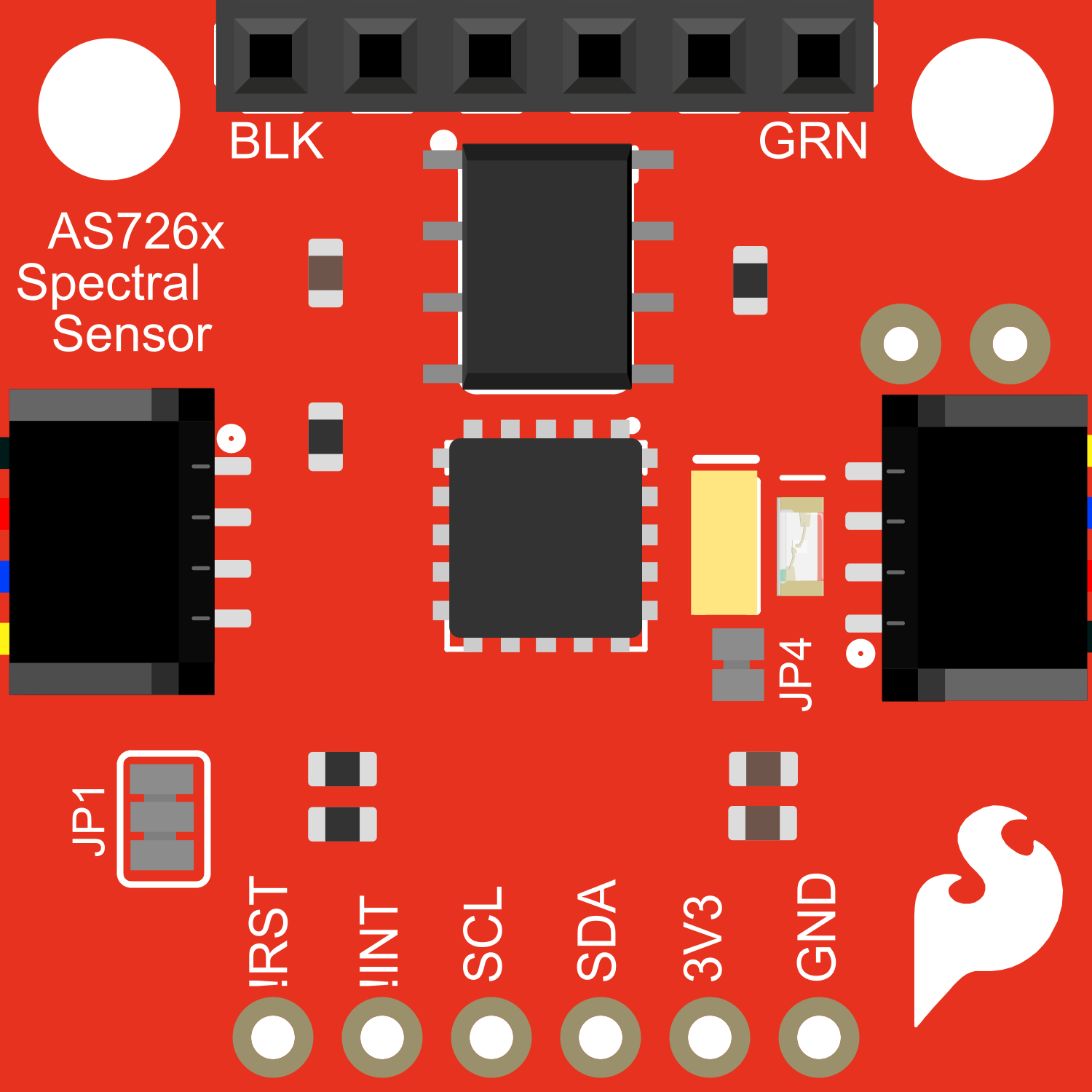
Pin Configuration and Descriptions

Pin Number Name Description
1 GND Ground connection
2 3V3 3.3V power supply input
3 SDA I2C data line
4 SCL I2C clock line
5 TX UART transmit (optional use)
6 RX UART receive (optional use)
7 INT Interrupt output (active low)
8 RST Reset input (active low)

Usage Instructions

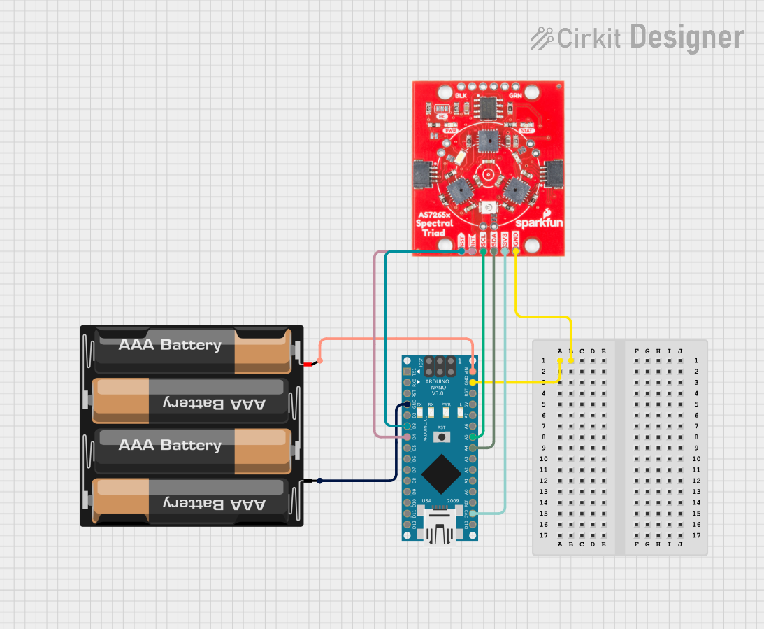
Integration into a Circuit

  1. Powering the Sensor: Connect the 3V3 pin to a 3.3V power source and GND to ground.
  2. I2C Communication: Connect SDA and SCL to your microcontroller's I2C data and clock lines respectively.
  3. Qwiic Connect System: Alternatively, use the Qwiic connect system to link the sensor with other Qwiic compatible devices without manual wiring.

Important Considerations and Best Practices

  • Ensure that the power supply is stable and within the specified voltage range.
  • Avoid exposing the sensor to direct sunlight or high-intensity light sources that could saturate the sensor.
  • For accurate readings, calibrate the sensor for the specific light conditions of your application.
  • Use pull-up resistors on the I2C lines if they are not already present on your microcontroller board.

Troubleshooting and FAQs

Common Issues

  • No Data Received: Check the I2C connections and ensure that the correct I2C address is being used.
  • Inaccurate Readings: Verify that the sensor is not being exposed to light outside its spectral range and that it has been properly calibrated.
  • Intermittent Communication: Ensure that there are no loose connections and that the pull-up resistors are correctly installed on the I2C lines.

Solutions and Tips

  • If you encounter issues with the I2C communication, use an I2C scanner sketch to confirm the device's address.
  • For calibration, use a known light source and compare the sensor readings to a reference measurement.
  • In case of communication issues, check the solder joints on the Qwiic connectors and I2C lines for cold solder or short circuits.

FAQs

Q: Can the sensor be used with a 5V system? A: Yes, the sensor is 5V tolerant, but it is recommended to use a level shifter for the I2C lines when interfacing with a 5V microcontroller.

Q: How can I reset the sensor? A: You can reset the sensor by pulling the RST pin low.

Q: What is the default I2C address of the AS7262? A: The default I2C address is 0x49.

Example Code for Arduino UNO

Below is an example code snippet for initializing the AS7262 sensor and reading the spectral data using an Arduino UNO. Ensure you have installed the necessary SparkFun AS7262 Arduino library before uploading the code.

#include <Wire.h>
#include <SparkFun_AS726X.h>

AS726X as7262;

void setup() {
  Wire.begin();
  Serial.begin(115200);
  as7262.begin(Wire, AS726X_ADDRESS);
}

void loop() {
  // Take measurements
  as7262.takeMeasurements();

  // Read the values for each channel
  Serial.print("450nm: ");
  Serial.print(as7262.getViolet());
  Serial.print(" ");
  // ... Repeat for other channels

  // Print a newline and delay before the next reading
  Serial.println();
  delay(1000);
}

Remember to wrap the code comments to limit line length to 80 characters. This example demonstrates how to initialize the sensor and read the spectral data. For a complete implementation, including all channels and error handling, refer to the SparkFun AS7262 Arduino library documentation.