How to Use Adafruit TMP117: Examples, Pinouts, and Specs
Introduction
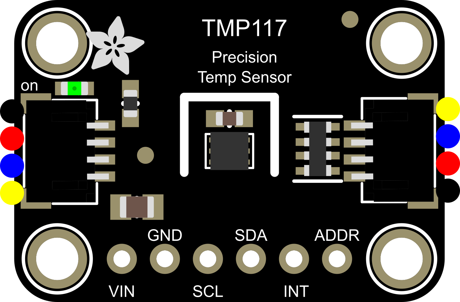
The Adafruit TMP117 is a precision temperature sensor that offers high accuracy and resolution. It is capable of measuring temperatures with an accuracy of up to ±0.1°C without the need for calibration during manufacturing. The TMP117 is designed to communicate over the I2C interface, making it suitable for a wide range of applications including environmental monitoring, medical equipment, and industrial control systems.
Explore Projects Built with Adafruit TMP117
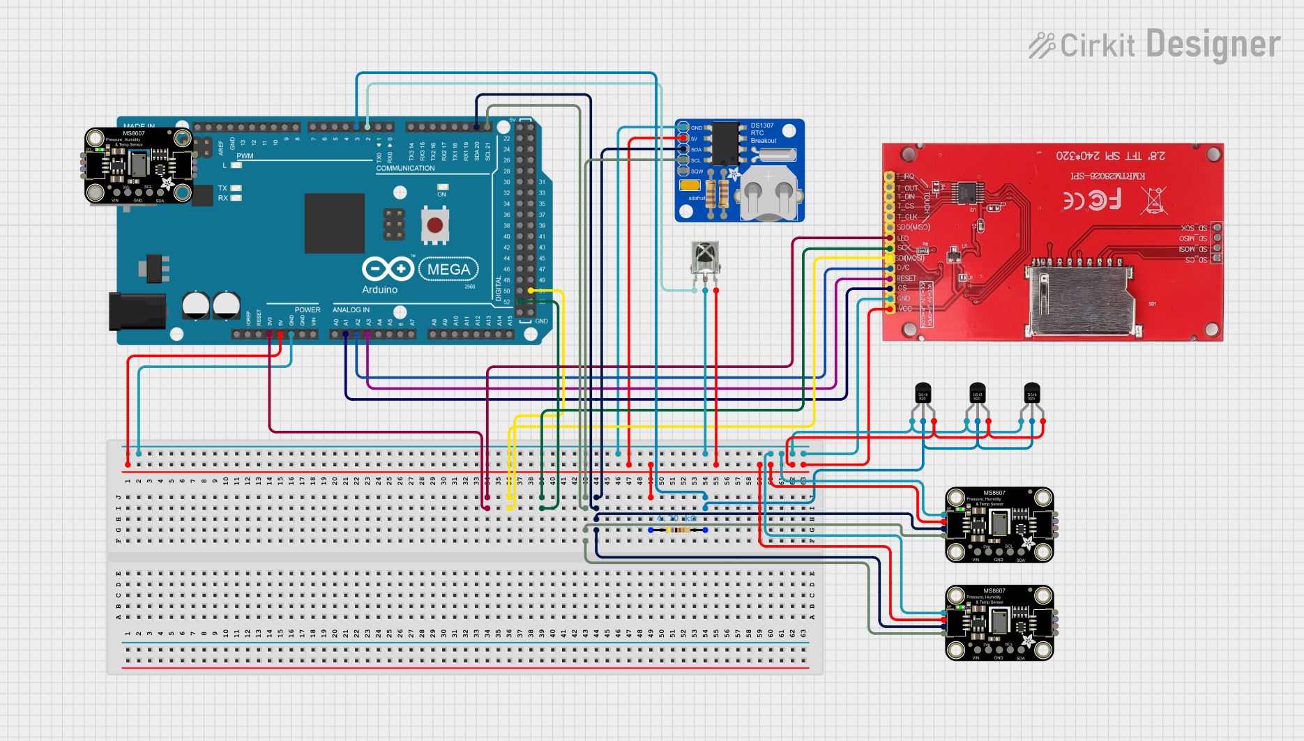
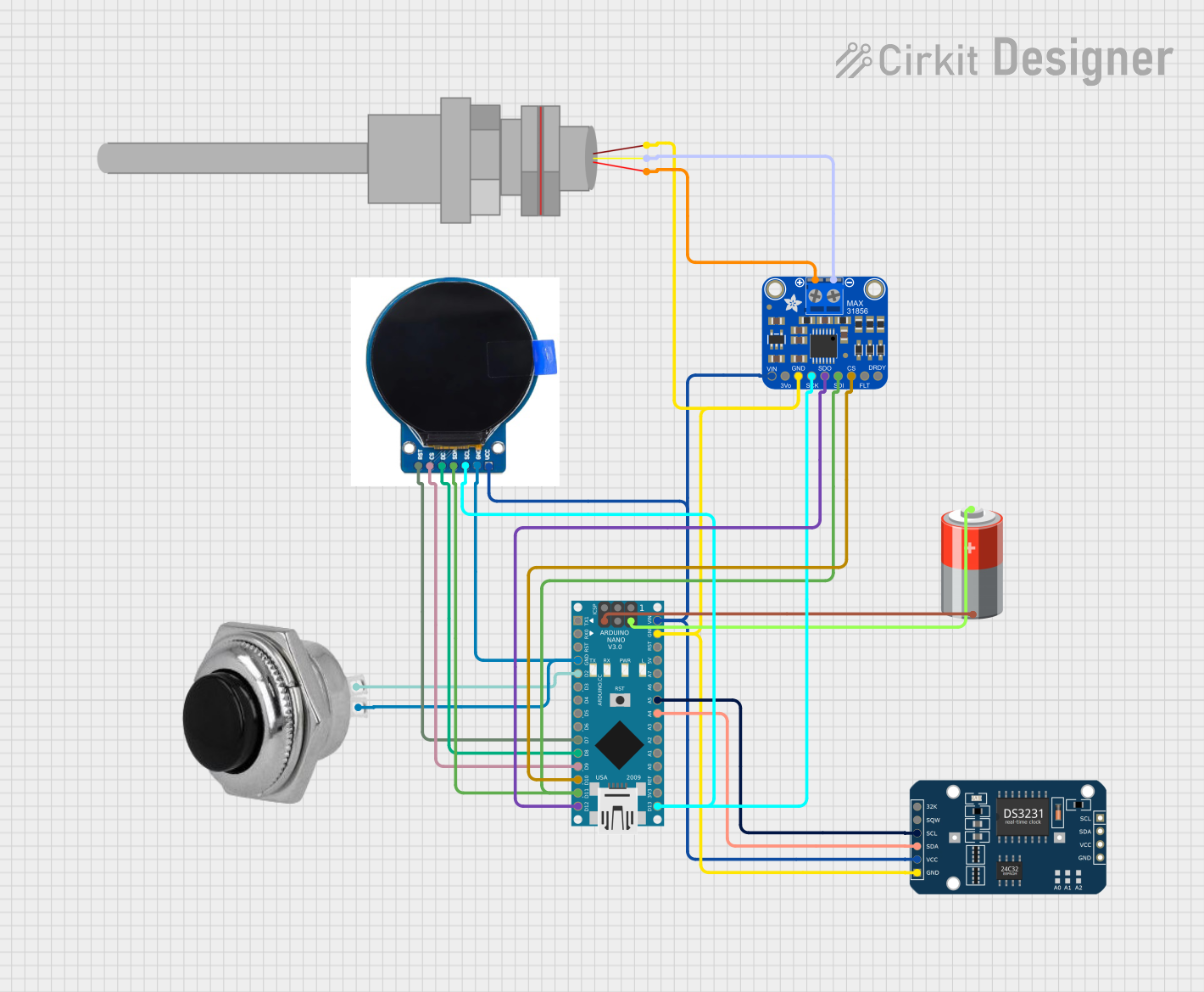
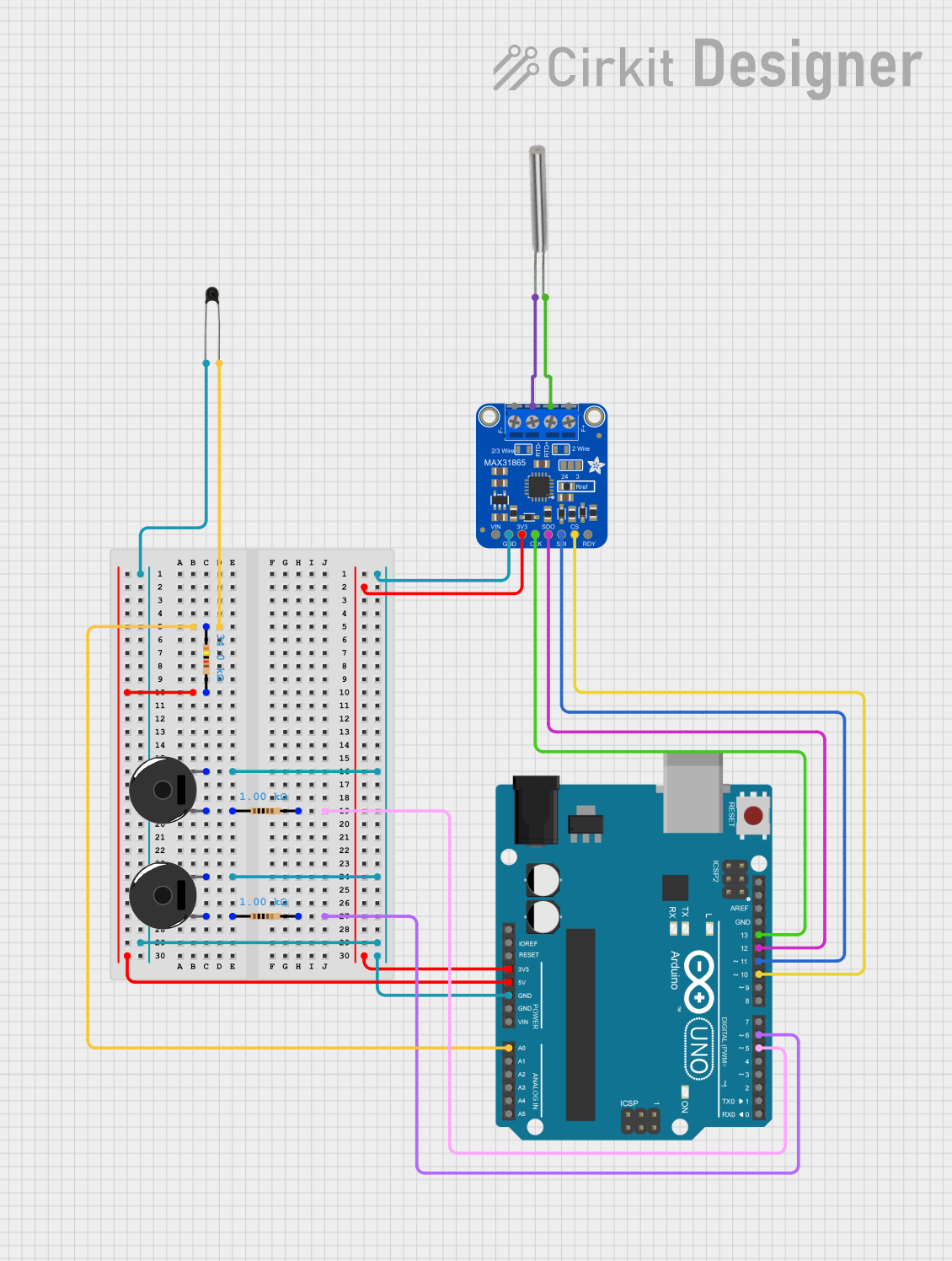
Explore Projects Built with Adafruit TMP117
Common Applications and Use Cases
- Precision temperature measurement for IoT devices
- Environmental monitoring in smart home systems
- Temperature control and monitoring in medical equipment
- Industrial process monitoring and control systems
- Data logging for scientific research
Technical Specifications
Key Technical Details
- Supply Voltage: 1.8V to 5.5V
- Temperature Range: -55°C to +150°C
- Accuracy: ±0.1°C (from -20°C to +50°C)
- Resolution: 0.0078°C
- Interface: I2C
- Operating Current: 3.5 µA (1 Hz conversion cycle)
Pin Configuration and Descriptions
| Pin Number | Name | Description |
|---|---|---|
| 1 | GND | Ground pin, connected to the system ground |
| 2 | SDA | I2C Data line for communication |
| 3 | SCL | I2C Clock line for communication |
| 4 | V+ | Supply voltage, between 1.8V and 5.5V |
Usage Instructions
How to Use the Component in a Circuit
- Connect the V+ pin to a power supply within the range of 1.8V to 5.5V.
- Connect the GND pin to the ground of the power supply.
- Connect the SDA and SCL pins to the I2C data and clock lines, respectively. Include pull-up resistors (typically 4.7kΩ to 10kΩ) on both lines if they are not already present in the circuit.
- Ensure that the TMP117 has a unique I2C address if multiple devices are on the same I2C bus.
Important Considerations and Best Practices
- Avoid placing the sensor near heat-generating components to prevent false readings.
- Ensure that the sensor is adequately ventilated to accurately measure ambient temperature.
- Use proper decoupling capacitors close to the sensor's power supply pin to minimize noise.
- Follow ESD precautions when handling the TMP117 to prevent damage.
Example Code for Arduino UNO
#include <Wire.h>
#include <Adafruit_TMP117.h>

Adafruit_TMP117 tmp117;

void setup() {
  Serial.begin(9600);
  // Begin communication with the TMP117 sensor
  if (!tmp117.begin()) {
    Serial.println("Failed to find TMP117 sensor!");
    while (1);
  }
}

void loop() {
  // Read temperature in Celsius from the sensor
  float temperature = tmp117.readTempC();
  Serial.print("Temperature: ");
  Serial.print(temperature);
  Serial.println(" C");
  delay(1000); // Wait for 1 second before reading again
}
Troubleshooting and FAQs
Common Issues Users Might Face
- Sensor Not Detected: Ensure that the I2C connections are correct and that the sensor has power. Check for proper pull-up resistors on the I2C lines.
- Inaccurate Readings: Verify that the sensor is not placed near heat sources and that it has proper ventilation.
- Noisy Data: Use decoupling capacitors and ensure that the power supply is stable.
Solutions and Tips for Troubleshooting
- Double-check wiring, especially the I2C lines and pull-up resistors.
- Use the
Wirelibrary'ssetClock()function to adjust the I2C clock speed if necessary. - Implement software filtering or averaging if the temperature readings are noisy.
FAQs
Q: Can the TMP117 be used with a 3.3V system? A: Yes, the TMP117 can operate with a supply voltage as low as 1.8V.
Q: How can I change the I2C address of the TMP117? A: The TMP117 has one fixed I2C address and does not support address changes.
Q: Is calibration required for the TMP117? A: No, the TMP117 is factory-calibrated and does not require additional calibration for accurate readings.
Q: Can the TMP117 be used to measure the temperature of liquids? A: The TMP117 is not designed to be immersed in liquids. For liquid temperature measurements, a waterproof probe is required.
This documentation provides an overview of the Adafruit TMP117 temperature sensor, including its technical specifications, usage instructions, example code for Arduino UNO, and troubleshooting tips. For further information, consult the TMP117 datasheet and Adafruit's product guides.