How to Use Pololu D24V6F5: Examples, Pinouts, and Specs
Introduction
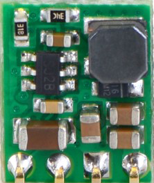
The Pololu D24V6F5 is a compact, high-efficiency DC-DC buck converter designed to step down a higher input voltage to a stable 5V output. With its ability to deliver up to 6A of output current, this regulator is ideal for powering devices that require a reliable 5V supply, such as microcontrollers, sensors, and other electronic components. Its small form factor and high efficiency make it suitable for a wide range of applications, including robotics, embedded systems, and portable electronics.
Explore Projects Built with Pololu D24V6F5
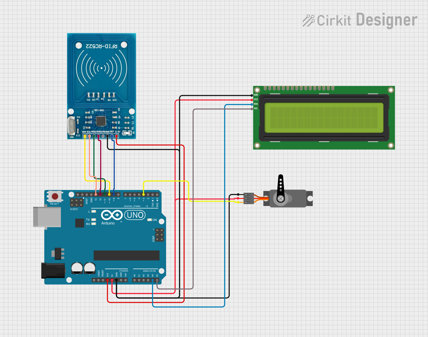


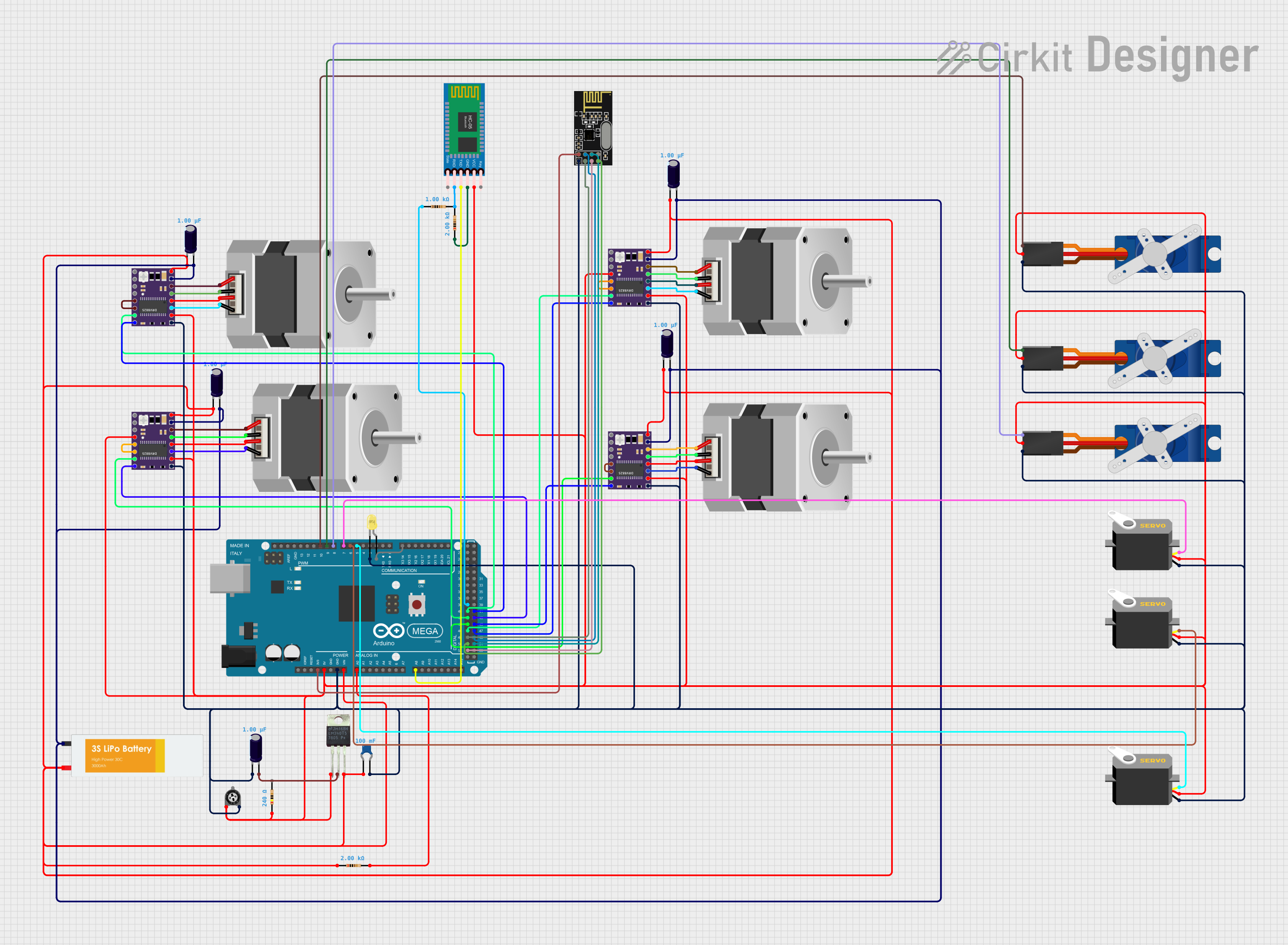
Explore Projects Built with Pololu D24V6F5
Common Applications
- Powering microcontrollers (e.g., Arduino, Raspberry Pi, ESP32)
- Supplying 5V to sensors, servos, and other peripherals
- Battery-powered systems requiring efficient voltage regulation
- Robotics and automation projects
- Portable electronic devices
Technical Specifications
The following table outlines the key technical details of the Pololu D24V6F5:
| Parameter | Value |
|---|---|
| Input Voltage Range | 5.1V to 38V |
| Output Voltage | 5V ± 4% |
| Maximum Output Current | 6A |
| Efficiency | Up to 95% (depending on load) |
| Quiescent Current | < 1 mA |
| Switching Frequency | ~500 kHz |
| Dimensions | 0.7" × 0.8" × 0.3" (18 × 20 × 8 mm) |
| Weight | 1.5 g |
| Operating Temperature | -40°C to +85°C |
Pin Configuration and Descriptions
The Pololu D24V6F5 has six pins, as described in the table below:
| Pin | Name | Description |
|---|---|---|
| 1 | VIN | Input voltage pin. Connect to the positive terminal of the input power source. |
| 2 | GND | Ground pin. Connect to the negative terminal of the input power source. |
| 3 | VOUT | Regulated 5V output pin. Connect to the load requiring 5V. |
| 4 | GND | Ground pin. Connect to the ground of the load. |
| 5 | SHDN | Shutdown pin. Drive low (or leave floating) to disable the regulator. |
| 6 | PG | Power good indicator. Outputs high when the output voltage is in regulation. |
Usage Instructions
How to Use the Pololu D24V6F5 in a Circuit
Connect the Input Voltage:
- Connect the VIN pin to the positive terminal of your power source (e.g., battery or power supply).
- Connect the GND pin to the negative terminal of your power source.
Connect the Output Voltage:
- Connect the VOUT pin to the positive terminal of your load (e.g., microcontroller, sensor).
- Connect the GND pin to the ground of your load.
Optional Connections:
- Use the SHDN pin to enable or disable the regulator. Leave it floating or drive it low to disable the output. Drive it high (above 2.3V) to enable the regulator.
- Use the PG pin to monitor the output voltage. This pin will output a high signal when the output voltage is within the specified range.
Verify Connections:
- Double-check all connections to ensure proper polarity and secure wiring.
Power On:
- Apply power to the input. The regulator will step down the input voltage to a stable 5V output.
Important Considerations and Best Practices
- Input Voltage Range: Ensure the input voltage is within the specified range (5.1V to 38V). Exceeding this range may damage the regulator.
- Heat Dissipation: At high currents, the regulator may generate heat. Ensure adequate ventilation or use a heatsink if necessary.
- Capacitors: For optimal performance, use low-ESR capacitors on the input and output. Pololu recommends a 33 µF or larger capacitor on the input and a 47 µF or larger capacitor on the output.
- Load Requirements: Ensure the load does not exceed the maximum output current of 6A.
Example: Using the Pololu D24V6F5 with an Arduino UNO
The Pololu D24V6F5 can be used to power an Arduino UNO from a 12V battery. Follow these steps:
- Connect the VIN pin of the regulator to the positive terminal of the 12V battery.
- Connect the GND pin of the regulator to the negative terminal of the battery.
- Connect the VOUT pin of the regulator to the 5V pin of the Arduino UNO.
- Connect the GND pin of the regulator to the GND pin of the Arduino UNO.
Here is an example Arduino sketch to blink an LED while powered by the Pololu D24V6F5:
// Example Arduino code to blink an LED
// This code assumes the Arduino is powered by the Pololu D24V6F5 regulator.

const int ledPin = 13; // Pin connected to the onboard LED

void setup() {
  pinMode(ledPin, OUTPUT); // Set the LED pin as an output
}

void loop() {
  digitalWrite(ledPin, HIGH); // Turn the LED on
  delay(1000);                // Wait for 1 second
  digitalWrite(ledPin, LOW);  // Turn the LED off
  delay(1000);                // Wait for 1 second
}
Troubleshooting and FAQs
Common Issues and Solutions
No Output Voltage:
- Verify that the input voltage is within the specified range (5.1V to 38V).
- Check the SHDN pin. Ensure it is not floating or driven low.
- Inspect all connections for proper polarity and secure wiring.
Overheating:
- Ensure the load does not exceed the maximum output current of 6A.
- Improve ventilation or add a heatsink to dissipate heat.
Output Voltage Fluctuations:
- Add low-ESR capacitors to the input and output as recommended.
- Check for loose or poor connections.
PG Pin Not High:
- Ensure the output voltage is within the specified range (5V ± 4%).
- Verify that the load is not drawing excessive current.
FAQs
Q: Can I use the Pololu D24V6F5 to power a Raspberry Pi?
A: Yes, the Pololu D24V6F5 can provide a stable 5V output suitable for powering a Raspberry Pi. Ensure the input voltage is within the specified range and the load does not exceed 6A.
Q: What happens if the input voltage drops below 5.1V?
A: If the input voltage drops below 5.1V, the regulator may not maintain a stable 5V output, and the PG pin will indicate that the output is out of regulation.
Q: Can I leave the SHDN pin floating?
A: Yes, the SHDN pin can be left floating, as it is internally pulled up. However, driving it high or low provides more control over enabling or disabling the regulator.
Q: Is reverse polarity protection included?
A: No, the Pololu D24V6F5 does not include reverse polarity protection. Ensure correct polarity to avoid damage.