How to Use Relay: Examples, Pinouts, and Specs
Introduction
A relay is an electromechanical switch that uses an electromagnetic coil to open or close a circuit. It allows a low-power signal to control a high-power circuit, making it an essential component in many electronic and electrical systems. Relays are widely used in applications such as home automation, industrial control systems, automotive electronics, and power distribution systems. They provide electrical isolation between the control circuit and the load, ensuring safety and reliability.
Explore Projects Built with Relay


Explore Projects Built with Relay
Technical Specifications
Below are the general technical specifications for a standard single-pole single-throw (SPST) relay. Specifications may vary depending on the specific relay model.
General Specifications
- Coil Voltage: 5V, 12V, or 24V DC (common values)
- Coil Current: Typically 30–100 mA
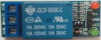
- Contact Rating: 10A at 250V AC or 10A at 30V DC
- Contact Type: SPST (Single Pole Single Throw) or SPDT (Single Pole Double Throw)
- Switching Time: 5–15 ms
- Dielectric Strength: 1000V AC (coil to contact)
- Insulation Resistance: >100 MΩ at 500V DC
- Mechanical Life: >10 million operations
- Electrical Life: >100,000 operations (at rated load)
Pin Configuration and Descriptions
The pin configuration of a typical 5V SPDT relay is as follows:
| Pin Name | Description |
|---|---|
| Coil (+) | Positive terminal of the electromagnetic coil. Connect to the control voltage. |
| Coil (-) | Negative terminal of the electromagnetic coil. Connect to ground. |
| Common (COM) | Common terminal for the relay switch. |
| Normally Open (NO) | Terminal that remains disconnected from COM when the relay is inactive. It connects to COM when the relay is activated. |
| Normally Closed (NC) | Terminal that remains connected to COM when the relay is inactive. It disconnects from COM when the relay is activated. |
Usage Instructions
How to Use the Relay in a Circuit
- Power the Coil: Connect the relay's coil terminals to a low-power control circuit. For example, use a 5V DC power source for a 5V relay.
- Control the Load: Connect the high-power load to the relay's COM and NO or NC terminals, depending on the desired behavior:
- Use the NO terminal if the load should be powered only when the relay is activated.
- Use the NC terminal if the load should be powered when the relay is inactive.
- Add a Flyback Diode: Place a flyback diode (e.g., 1N4007) across the coil terminals to protect the control circuit from voltage spikes caused by the relay's inductive load.
- Drive the Relay: Use a transistor or MOSFET to drive the relay if the control circuit cannot supply enough current to the coil. Connect the transistor's base/gate to the control signal, and connect the relay coil to the transistor's collector/drain.
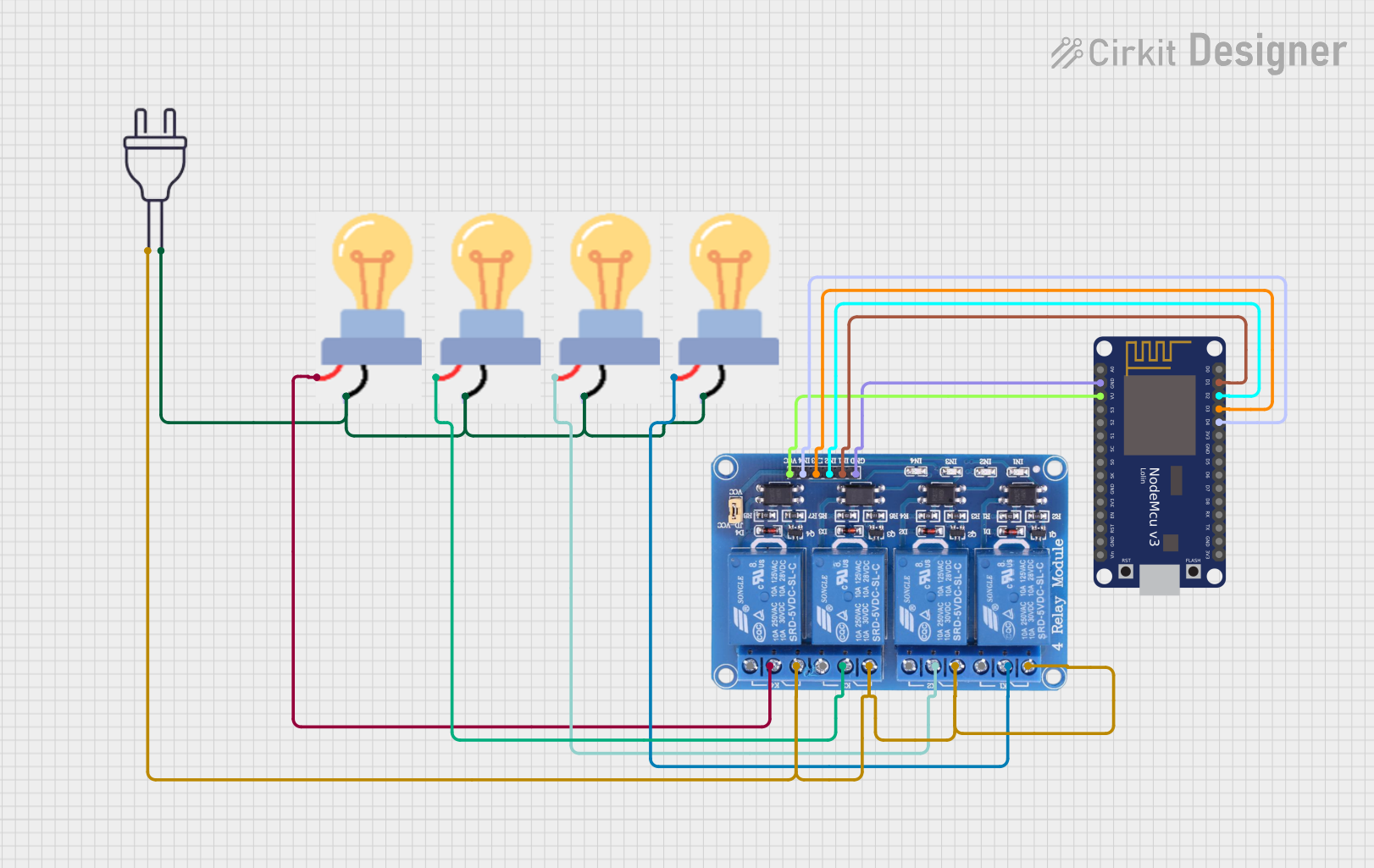
Example Circuit with Arduino UNO
Below is an example of how to control a 5V relay using an Arduino UNO:
// Define the relay pin
const int relayPin = 7; // Connect the relay module's IN pin to Arduino pin 7

void setup() {
  pinMode(relayPin, OUTPUT); // Set the relay pin as an output
  digitalWrite(relayPin, LOW); // Ensure the relay is off at startup
}

void loop() {
  digitalWrite(relayPin, HIGH); // Turn the relay on
  delay(1000); // Keep the relay on for 1 second
  digitalWrite(relayPin, LOW); // Turn the relay off
  delay(1000); // Keep the relay off for 1 second
}
Important Considerations and Best Practices
- Always check the relay's voltage and current ratings to ensure compatibility with your circuit.
- Use a flyback diode to protect the control circuit from voltage spikes.
- Avoid exceeding the relay's contact rating to prevent damage or failure.
- Ensure proper insulation and spacing between high-voltage and low-voltage sections of the circuit.
- For high-power applications, consider using relays with higher contact ratings or solid-state relays.
Troubleshooting and FAQs
Common Issues and Solutions
Relay Not Activating:
- Cause: Insufficient voltage or current to the coil.
- Solution: Verify the control voltage and current. Use a transistor or MOSFET driver if needed.
Relay Stuck in One State:
- Cause: Damaged or worn-out contacts.
- Solution: Replace the relay if the contacts are damaged.
Voltage Spikes Damaging the Circuit:
- Cause: Lack of a flyback diode across the coil.
- Solution: Add a flyback diode (e.g., 1N4007) across the coil terminals.
Relay Clicking Noise but No Load Switching:
- Cause: Incorrect wiring of the load or damaged contacts.
- Solution: Check the wiring and ensure the load is connected to the correct terminals (COM and NO/NC).
FAQs
Q: Can I use a relay to switch AC loads?
- A: Yes, relays can switch both AC and DC loads, provided the load does not exceed the relay's contact rating.
Q: What is the purpose of the flyback diode?
- A: The flyback diode protects the control circuit from voltage spikes generated when the relay coil is de-energized.
Q: Can I directly connect a relay to an Arduino pin?
- A: It depends on the relay's coil current. If the current exceeds the Arduino pin's limit (40 mA), use a transistor or MOSFET to drive the relay.
Q: How do I know if my relay is SPST or SPDT?
- A: Check the relay's datasheet or look for the number of terminals. SPST relays have 4 pins, while SPDT relays typically have 5 pins.