How to Use .38" AMP Guage: Examples, Pinouts, and Specs
Introduction
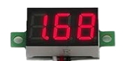
The Bayite .38" AMP Gauge is a compact analog meter designed to measure electrical current in a circuit. It features a needle that moves across a calibrated scale, providing a clear and precise visual representation of the current being measured. This gauge is ideal for applications requiring real-time current monitoring, such as in automotive systems, solar power setups, and DIY electronics projects.
Explore Projects Built with .38" AMP Guage


Explore Projects Built with .38" AMP Guage
Common Applications and Use Cases
- Monitoring current in automotive electrical systems
- Measuring current in solar panel installations
- DIY electronics and prototyping
- Battery charge and discharge monitoring
- General-purpose current measurement in low-voltage circuits
Technical Specifications
The Bayite .38" AMP Gauge is designed for ease of use and reliable performance. Below are its key technical details:
Key Specifications
| Parameter | Value |
|---|---|
| Measurement Range | 0 to 10A (or as specified) |
| Operating Voltage | 12V DC (typical) |
| Accuracy | ±2% of full scale |
| Display Type | Analog needle gauge |
| Dimensions | 0.38 inches (display size) |
| Mounting Style | Panel mount |
| Material | Durable plastic and metal |
Pin Configuration and Descriptions
The .38" AMP Gauge typically has two connection terminals for current measurement. These terminals are labeled as follows:
| Pin/Terminal | Description |
|---|---|
| Positive (+) | Connect to the positive side of the circuit being measured. |
| Negative (-) | Connect to the negative side of the circuit or ground. |
Note: Ensure proper polarity when connecting the gauge to avoid damage or incorrect readings.
Usage Instructions
How to Use the .38" AMP Gauge in a Circuit
- Determine the Measurement Point: Identify the part of the circuit where you want to measure the current.
- Connect the Terminals:
- Connect the positive terminal of the gauge to the positive side of the circuit.
- Connect the negative terminal to the negative side or ground.
- Power the Circuit: Once the gauge is connected, power the circuit. The needle will move to indicate the current flowing through the circuit.
- Read the Measurement: Observe the needle's position on the calibrated scale to determine the current value.
Important Considerations and Best Practices
- Polarity: Always connect the terminals with the correct polarity to avoid damage to the gauge.
- Current Range: Ensure the current in the circuit does not exceed the gauge's maximum rating (e.g., 10A). Exceeding this limit may damage the gauge or result in inaccurate readings.
- Shunt Resistor: For higher current measurements, use an appropriate shunt resistor as specified by the manufacturer.
- Mounting: Securely mount the gauge on a panel to prevent movement or vibration during operation.
- Environmental Conditions: Avoid exposing the gauge to extreme temperatures, moisture, or dust, as these conditions may affect its accuracy and longevity.
Example: Connecting to an Arduino UNO
While the .38" AMP Gauge is an analog device, it can be used in conjunction with an Arduino UNO to monitor current in a circuit. Below is an example of how to integrate the gauge with an Arduino setup:
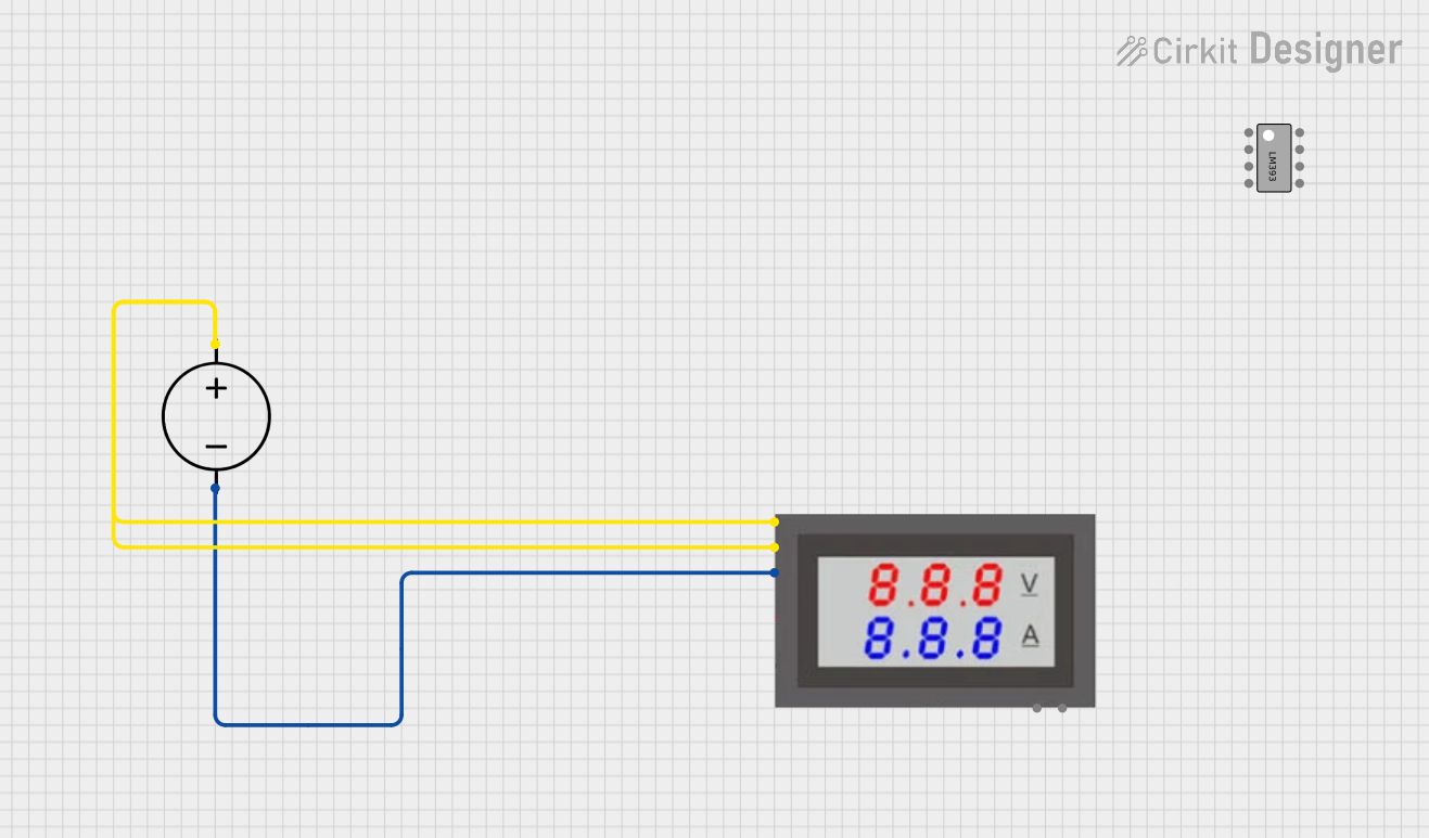
Circuit Diagram
- Connect the positive terminal of the gauge to the positive side of the load.
- Connect the negative terminal of the gauge to the ground of the Arduino and the load.
Arduino Code
The following code demonstrates how to read current values using an external current sensor (e.g., ACS712) and display the readings on the serial monitor. The .38" AMP Gauge can be used alongside this setup for visual monitoring.
// Example code for reading current using ACS712 sensor with Arduino UNO
// and using the .38" AMP Gauge for visual monitoring.

const int sensorPin = A0; // Analog pin connected to the current sensor
float sensitivity = 0.185; // Sensitivity for ACS712 (e.g., 185mV/A for 5A module)
float offsetVoltage = 2.5; // Offset voltage at 0A (typical for ACS712)
float current; // Variable to store the calculated current

void setup() {
  Serial.begin(9600); // Initialize serial communication
  pinMode(sensorPin, INPUT); // Set sensor pin as input
}

void loop() {
  int sensorValue = analogRead(sensorPin); // Read the analog value
  float voltage = (sensorValue / 1023.0) * 5.0; // Convert to voltage
  current = (voltage - offsetVoltage) / sensitivity; // Calculate current

  // Print the current value to the serial monitor
  Serial.print("Current: ");
  Serial.print(current);
  Serial.println(" A");

  delay(1000); // Wait for 1 second before the next reading
}
Note: The .38" AMP Gauge is connected in series with the load for real-time visual monitoring, while the Arduino reads current values using the ACS712 sensor.
Troubleshooting and FAQs
Common Issues and Solutions
| Issue | Possible Cause | Solution |
|---|---|---|
| Needle does not move | Incorrect wiring or no current flow | Check connections and ensure current is flowing. |
| Needle moves in the wrong direction | Reversed polarity | Swap the positive and negative connections. |
| Inaccurate readings | Exceeding current range or loose connections | Ensure current is within range and tighten connections. |
| Gauge does not fit in panel | Incorrect mounting size | Verify panel cutout dimensions before installation. |
FAQs
Can the .38" AMP Gauge measure AC current?
- No, this gauge is designed for DC current measurement only.
What happens if I exceed the maximum current rating?
- Exceeding the maximum rating may damage the gauge or result in inaccurate readings. Use a shunt resistor for higher currents.
Can I use this gauge with a microcontroller like Arduino?
- Yes, the gauge can be used for visual monitoring alongside a current sensor connected to the Arduino.
How do I calibrate the gauge?
- The gauge is factory-calibrated. If calibration is required, consult the manufacturer’s instructions.
By following this documentation, users can effectively integrate and utilize the Bayite .38" AMP Gauge in their projects.