Cirkit Designer Logo
Cirkit Designer
Your all-in-one circuit design IDE
Home / 
Component Documentation

How to Use LilyPad: Examples, Pinouts, and Specs

Image of LilyPad
Cirkit Designer LogoDesign with LilyPad in Cirkit Designer

Introduction

LilyPad is a wearable electronic platform specifically designed for e-textiles and soft circuits. It features a series of sewable microcontrollers, sensors, and other components that can be easily integrated into fabric. The circular design of LilyPad boards allows for easy sewing with conductive thread, making it ideal for creating interactive garments and wearable projects.

Explore Projects Built with LilyPad

Use Cirkit Designer to design, explore, and prototype these projects online. Some projects support real-time simulation. Click "Open Project" to start designing instantly!
LilyPad Arduino and Accelerometer-Based Wearable Fitness Tracker with Heart Rate Monitoring
Image of proj2: A project utilizing LilyPad in a practical application
This circuit is designed for wearable applications, featuring a LilyPad Arduino USB microcontroller that controls a chain of LED Pixel Boards and reads data from a Heart Pulse Sensor and a three-axis Accelerometer. It is capable of interactive LED displays synchronized with motion and heart rate data, suitable for dynamic wearable projects.
Cirkit Designer LogoOpen Project in Cirkit Designer
Lilygo 7670e-Based Smart Interface with LCD Display and Keypad
Image of Paower: A project utilizing LilyPad in a practical application
This circuit features a Lilygo 7670e microcontroller interfaced with a 16x2 I2C LCD for display, a 4X4 membrane matrix keypad for input, and an arcade button for additional control. It also includes a 4G antenna and a GPS antenna for communication and location tracking capabilities.
Cirkit Designer LogoOpen Project in Cirkit Designer
ESP8266 NodeMCU Wi-Fi Enabled OLED Display with RYLR896 Communication Module
Image of Smart Irrigation system Rx Side: A project utilizing LilyPad in a practical application
This circuit features an ESP8266 NodeMCU microcontroller connected to a 0.96" OLED display and an RYLR896 LoRa module. The ESP8266 communicates with the OLED via I2C protocol and interfaces with the LoRa module using UART, enabling wireless data transmission and display capabilities.
Cirkit Designer LogoOpen Project in Cirkit Designer
NodeMCU ESP8266 Controlled Drone with TFT Display and nRF24L01 Communication
Image of receiver/transmitter: A project utilizing LilyPad in a practical application
This circuit features a NodeMCU V3 ESP8266 microcontroller interfaced with an LCD TFT screen, an nRF24L01 wireless transceiver, and an Adafruit Analog 2-Axis Joystick. The NodeMCU collects joystick inputs and displays information on the TFT screen, while also communicating with other devices via the nRF24L01 module. The circuit is powered by a 9V battery, with the NodeMCU regulating the voltage for other components.
Cirkit Designer LogoOpen Project in Cirkit Designer

Explore Projects Built with LilyPad

Use Cirkit Designer to design, explore, and prototype these projects online. Some projects support real-time simulation. Click "Open Project" to start designing instantly!
Image of proj2: A project utilizing LilyPad in a practical application
LilyPad Arduino and Accelerometer-Based Wearable Fitness Tracker with Heart Rate Monitoring
This circuit is designed for wearable applications, featuring a LilyPad Arduino USB microcontroller that controls a chain of LED Pixel Boards and reads data from a Heart Pulse Sensor and a three-axis Accelerometer. It is capable of interactive LED displays synchronized with motion and heart rate data, suitable for dynamic wearable projects.
Cirkit Designer LogoOpen Project in Cirkit Designer
Image of Paower: A project utilizing LilyPad in a practical application
Lilygo 7670e-Based Smart Interface with LCD Display and Keypad
This circuit features a Lilygo 7670e microcontroller interfaced with a 16x2 I2C LCD for display, a 4X4 membrane matrix keypad for input, and an arcade button for additional control. It also includes a 4G antenna and a GPS antenna for communication and location tracking capabilities.
Cirkit Designer LogoOpen Project in Cirkit Designer
Image of Smart Irrigation system Rx Side: A project utilizing LilyPad in a practical application
ESP8266 NodeMCU Wi-Fi Enabled OLED Display with RYLR896 Communication Module
This circuit features an ESP8266 NodeMCU microcontroller connected to a 0.96" OLED display and an RYLR896 LoRa module. The ESP8266 communicates with the OLED via I2C protocol and interfaces with the LoRa module using UART, enabling wireless data transmission and display capabilities.
Cirkit Designer LogoOpen Project in Cirkit Designer
Image of receiver/transmitter: A project utilizing LilyPad in a practical application
NodeMCU ESP8266 Controlled Drone with TFT Display and nRF24L01 Communication
This circuit features a NodeMCU V3 ESP8266 microcontroller interfaced with an LCD TFT screen, an nRF24L01 wireless transceiver, and an Adafruit Analog 2-Axis Joystick. The NodeMCU collects joystick inputs and displays information on the TFT screen, while also communicating with other devices via the nRF24L01 module. The circuit is powered by a 9V battery, with the NodeMCU regulating the voltage for other components.
Cirkit Designer LogoOpen Project in Cirkit Designer

Common Applications and Use Cases

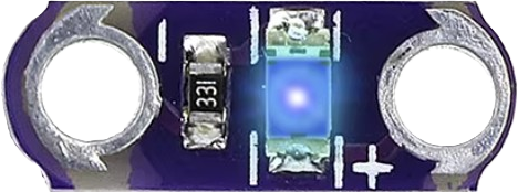
  • Wearable technology, such as light-up clothing or accessories
  • Interactive fashion and art installations
  • Fitness and health monitoring devices
  • Educational projects for learning about electronics and programming
  • Prototyping soft circuits and e-textile designs

Technical Specifications

Below are the key technical details for the LilyPad main board (e.g., LilyPad Arduino 328 Main Board):

General Specifications

  • Microcontroller: ATmega328P
  • Operating Voltage: 2.7V - 5.5V
  • Input Voltage: 2.7V - 5.5V
  • Digital I/O Pins: 14 (6 PWM outputs)
  • Analog Input Pins: 6
  • Flash Memory: 32 KB (2 KB used by bootloader)
  • SRAM: 2 KB
  • EEPROM: 1 KB
  • Clock Speed: 8 MHz (internal oscillator)
  • Dimensions: 50 mm diameter
  • Weight: ~5 g

Pin Configuration and Descriptions

The LilyPad board has several pins for connecting components. Below is a table describing the pin layout:

Pin Type Description
0-13 Digital I/O General-purpose digital input/output pins. Pins 3, 5, 6, 9, 10, and 11 support PWM.
A0-A5 Analog Input Analog input pins for reading sensor data. Can also be used as digital I/O pins.
+ Power (VCC) Positive voltage supply pin (2.7V - 5.5V).
- Ground (GND) Ground connection for the circuit.
RST Reset Resets the microcontroller.

Usage Instructions

How to Use the LilyPad in a Circuit

  1. Powering the LilyPad:

    • Use a coin cell battery, LiPo battery, or a regulated power supply (2.7V - 5.5V).
    • Connect the positive terminal of the power source to the + pin and the negative terminal to the - pin.
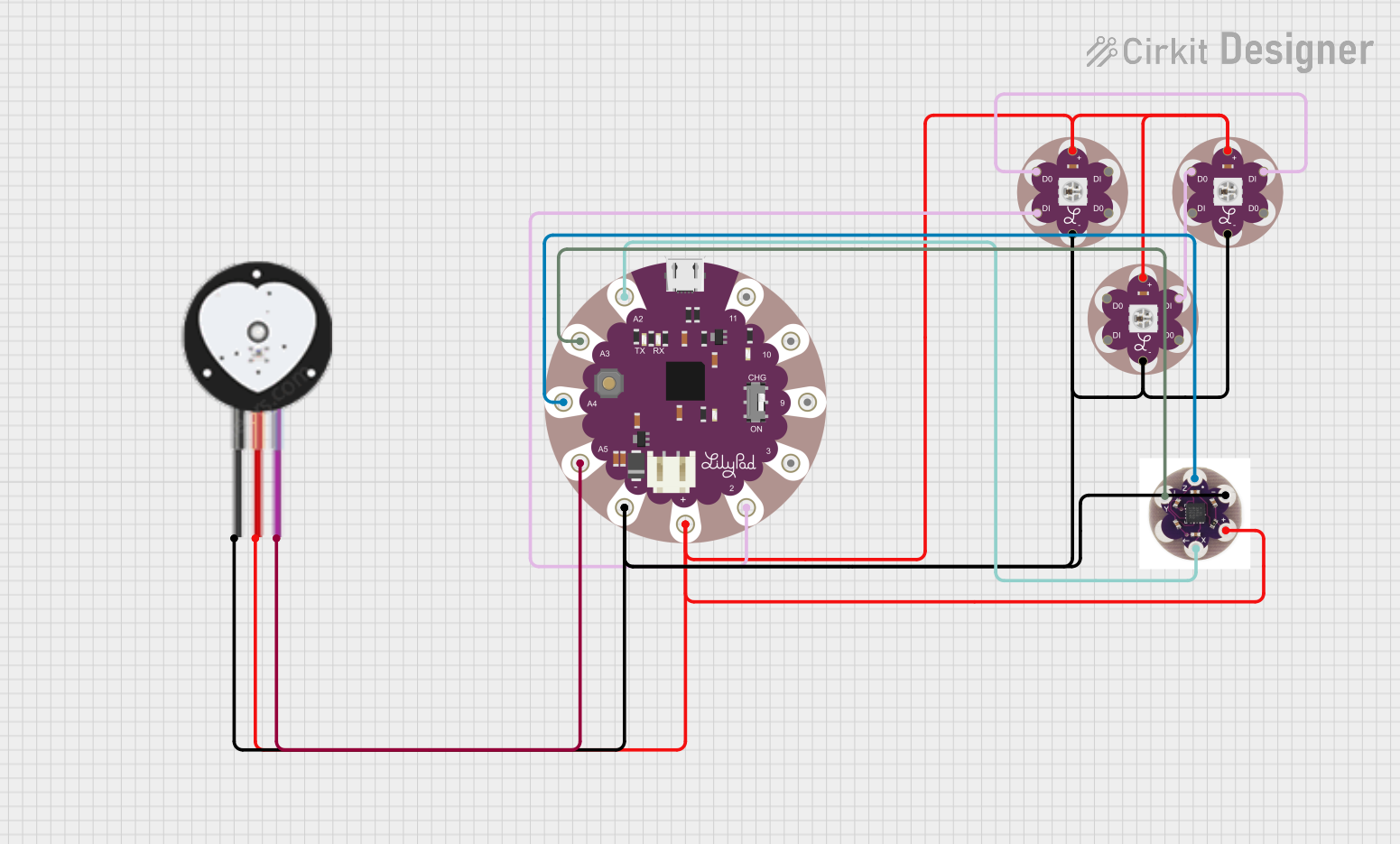
  2. Connecting Components:

    • Use conductive thread to sew connections between the LilyPad pins and external components (e.g., LEDs, sensors).
    • Ensure tight and secure stitches to maintain good electrical conductivity.
  3. Programming the LilyPad:

    • Connect the LilyPad to your computer using an FTDI adapter or USB-to-serial converter.
    • Open the Arduino IDE, select "LilyPad Arduino" as the board, and upload your code.

Important Considerations and Best Practices

  • Avoid overlapping conductive threads to prevent short circuits.
  • Use insulating fabric or tape to separate conductive traces if they cross.
  • Test connections with a multimeter before powering the circuit.
  • When sewing, ensure the conductive thread does not fray, as this can cause poor connections.

Example Code for Arduino UNO-Compatible LilyPad

Below is an example code to blink an LED connected to pin 13 of the LilyPad:

// Example: Blink an LED connected to pin 13 on the LilyPad
// This code will turn the LED on for 1 second, then off for 1 second.

void setup() {
  pinMode(13, OUTPUT); // Set pin 13 as an output pin
}

void loop() {
  digitalWrite(13, HIGH); // Turn the LED on
  delay(1000);            // Wait for 1 second
  digitalWrite(13, LOW);  // Turn the LED off
  delay(1000);            // Wait for 1 second
}

Troubleshooting and FAQs

Common Issues and Solutions

  1. The LilyPad is not powering on:

    • Check the battery or power source for sufficient voltage.
    • Ensure the + and - connections are secure and not reversed.
  2. The LilyPad is not recognized by the computer:

    • Verify that the FTDI adapter or USB-to-serial converter is properly connected.
    • Install the necessary drivers for the FTDI adapter.
    • Ensure the correct board and port are selected in the Arduino IDE.
  3. Components are not functioning as expected:

    • Check the connections for loose or frayed conductive thread.
    • Use a multimeter to test continuity between the LilyPad pins and the components.
    • Ensure the code uploaded to the LilyPad is correct and matches the circuit design.

FAQs

  • Can I wash garments with a LilyPad circuit?
    Yes, but you must remove the power source and ensure all components are washable. Hand washing is recommended.

  • What type of thread should I use?
    Use conductive thread specifically designed for e-textiles. Avoid regular thread for electrical connections.

  • Can I connect multiple sensors to the LilyPad?
    Yes, you can connect multiple sensors to the analog or digital pins, but ensure the total current draw does not exceed the power supply limits.

By following this documentation, you can successfully integrate the LilyPad into your wearable electronics projects!