How to Use Crystal 12MHz: Examples, Pinouts, and Specs
Introduction
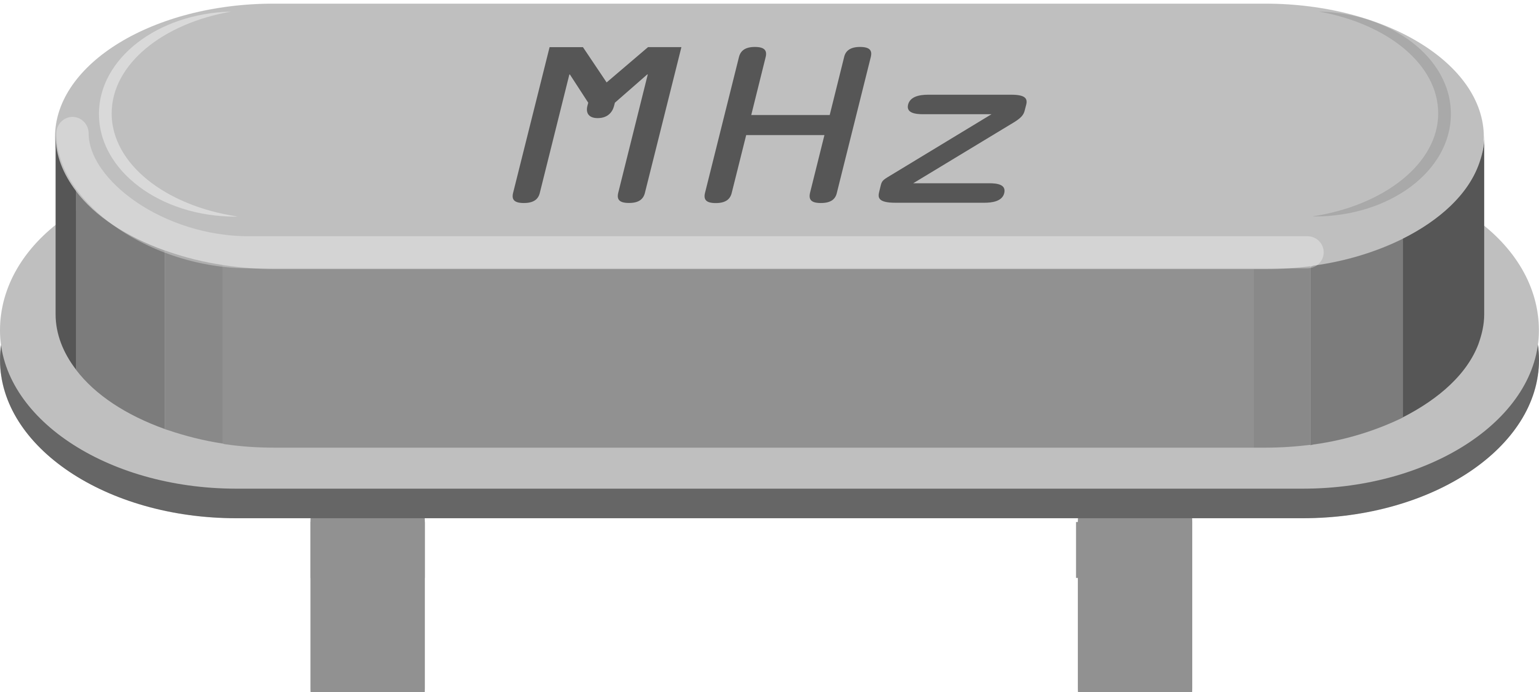
A 12MHz Crystal Oscillator is a passive electronic component that uses the mechanical resonance of a vibrating crystal to create an electrical signal with a precise frequency. This frequency is commonly used in microcontrollers and other digital integrated circuits to provide a stable clock signal.
Explore Projects Built with Crystal 12MHz
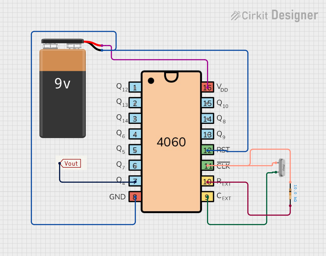

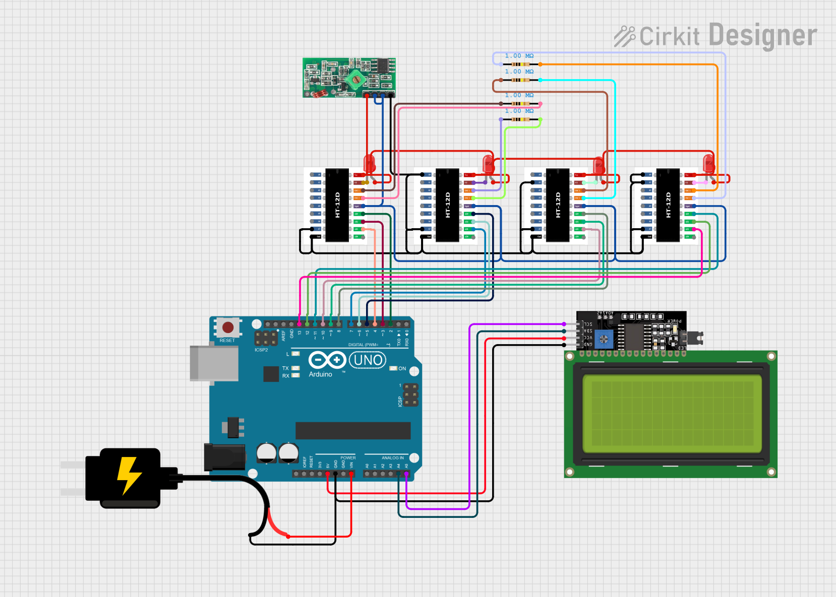

Explore Projects Built with Crystal 12MHz
Common Applications and Use Cases:
- Microcontroller clock source
- Real-time clocks
- Frequency synthesis and modulation
- Precision timing in communication systems
Technical Specifications
Key Technical Details:
- Frequency: 12MHz
- Frequency Tolerance: ±30 ppm
- Load Capacitance: 18 pF
- Drive Level: 1 mW (typical)
- Operating Temperature Range: -10°C to +60°C
- Aging: ±3 ppm/year
Pin Configuration and Descriptions:
| Pin Number | Description |
|---|---|
| 1 | Connection point 1 (Input/Output) |
| 2 | Ground (GND) or Case |
Usage Instructions
How to Use the Component in a Circuit:
- Power Supply: Connect the crystal across the oscillator pins of the microcontroller or integrated circuit (IC). Typically, these are labeled as
XTAL1andXTAL2orOSC_INandOSC_OUT. - Load Capacitors: Connect two capacitors from each pin of the crystal to ground. The value of these capacitors depends on the crystal's load capacitance and the input capacitance of the oscillator circuit.
- Grounding: Ensure that the crystal case (if present) is connected to the ground to minimize noise.
Important Considerations and Best Practices:
- Mounting: Keep the crystal and its load capacitors as close as possible to the oscillator pins to minimize stray capacitance and inductance.
- Temperature: Operate the crystal within its specified temperature range to maintain frequency accuracy.
- Handling: Crystals are sensitive to mechanical stress and shock. Handle them with care during installation.
Troubleshooting and FAQs
Common Issues Users Might Face:
- Inaccurate Clock Frequency: Check the load capacitors and ensure they are of the correct value. Also, verify that the crystal is operating within its specified temperature range.
- Oscillator Not Starting: Ensure that the crystal is properly seated and soldered. Check for short circuits or open connections.
Solutions and Tips for Troubleshooting:
- Check Solder Joints: Cold or dry solder joints can affect the oscillator's performance. Re-solder if necessary.
- Inspect Load Capacitors: Verify that the capacitors are not damaged and are of the correct value.
- Avoid Physical Stress: Do not apply excessive force to the crystal during installation.
FAQs:
Q: Can I use a 12MHz crystal with any microcontroller? A: Most microcontrollers can use a 12MHz crystal, but always check the datasheet of your specific microcontroller for compatibility.
Q: What happens if I use the wrong load capacitors? A: Using incorrect load capacitors can result in the oscillator not starting or the frequency being off. Always use the recommended capacitance values.
Q: How does temperature affect the crystal's frequency? A: Crystals are sensitive to temperature changes, which can cause frequency drift. Use temperature-compensated crystals if your application requires high precision.
Example Code for Arduino UNO
// Example code to set up a 12MHz external crystal with an Arduino UNO

void setup() {
  // Assuming the Arduino is running on an external 12MHz crystal
  // No specific code is needed to set up the crystal as the system clock
  // The below function initializes the serial communication at 9600 baud rate
  Serial.begin(9600);
}

void loop() {
  // Your code here
  Serial.println("12MHz Crystal Oscillator is functioning.");
  // A delay to make the message readable
  delay(1000);
}
Note: The Arduino UNO typically uses a 16MHz crystal. To use a 12MHz crystal, you would need to burn the bootloader with the appropriate clock settings or adjust the clock prescalers in your code. This example assumes that such changes have already been made.
Remember to always consult the datasheet of the specific crystal you are using for precise information and recommendations.