
How to Use Voltage Regulator: Examples, Pinouts, and Specs

 Design with Voltage Regulator in Cirkit Designer
Introduction
A voltage regulator is an electronic component designed to maintain a constant output voltage regardless of variations in input voltage or load conditions. It ensures a stable power supply to electronic circuits, protecting sensitive components from voltage fluctuations. Voltage regulators are widely used in power supplies, battery-operated devices, and embedded systems to provide reliable and consistent voltage levels.
Explore Projects Built with Voltage Regulator
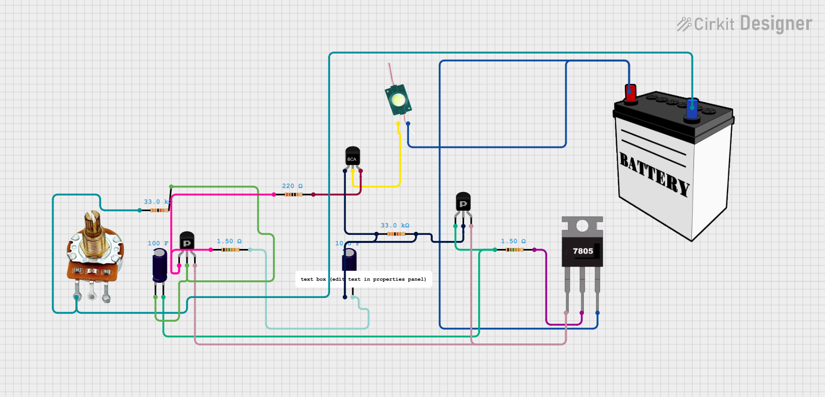 Open Project in Cirkit Designer
 Open Project in Cirkit Designer
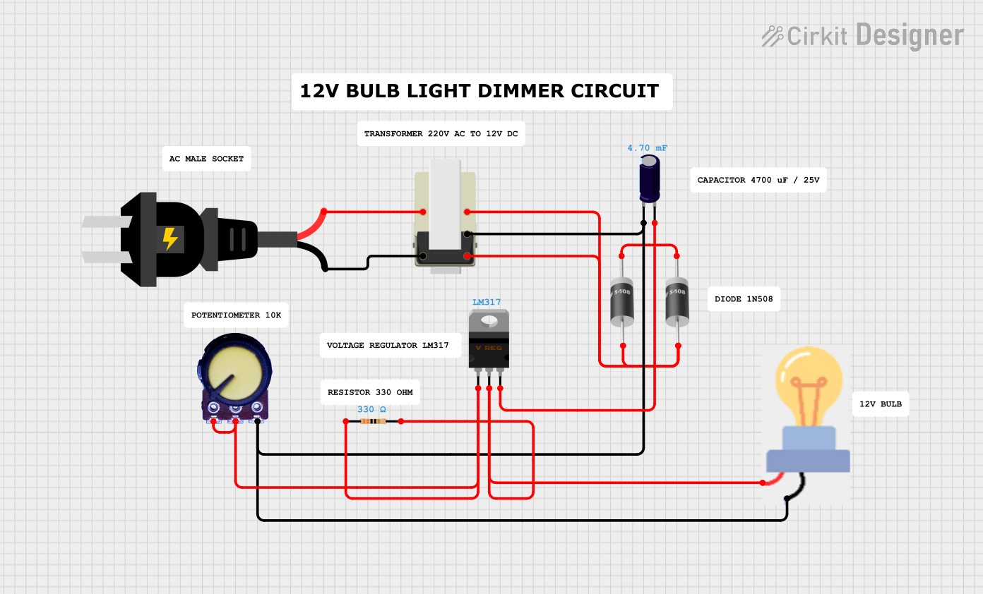 Open Project in Cirkit Designer
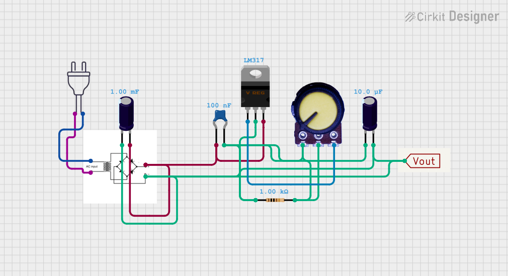 Open Project in Cirkit Designer
Explore Projects Built with Voltage Regulator
Open Project in Cirkit DesignerOpen Project in Cirkit DesignerOpen Project in Cirkit DesignerOpen Project in Cirkit DesignerCommon Applications and Use Cases
- Power supplies for electronic devices
- Voltage stabilization in battery-powered systems
- Microcontroller-based projects (e.g., Arduino, Raspberry Pi)
- Protection of sensitive components from voltage spikes
- Automotive electronics and industrial equipment
Technical Specifications
Voltage regulators come in various types, such as linear regulators and switching regulators. Below are the general technical specifications for a common linear voltage regulator, the LM7805 (5V fixed output regulator):
Key Technical Details
- Input Voltage Range: 7V to 35V
- Output Voltage: 5V (fixed)
- Output Current: Up to 1.5A
- Dropout Voltage: Typically 2V
- Quiescent Current: 5-8 mA
- Thermal Shutdown: Yes
- Short-Circuit Protection: Yes
- Operating Temperature Range: -40°C to +125°C
Pin Configuration and Descriptions
The LM7805 voltage regulator has three pins, as described in the table below:
| Pin Number | Name | Description |
|---|---|---|
| 1 | Input (IN) | Connects to the unregulated input voltage source |
| 2 | Ground (GND) | Common ground for input and output |
| 3 | Output (OUT) | Provides the regulated 5V output |
Usage Instructions
How to Use the Voltage Regulator in a Circuit
Connect the Input Voltage:
- Attach the unregulated DC voltage source (e.g., 9V battery or adapter) to the Input (IN) pin.
- Ensure the input voltage is at least 2V higher than the desired output voltage (e.g., 7V minimum for a 5V output).
Connect the Ground:
- Connect the Ground (GND) pin to the circuit's ground.
Connect the Output Voltage:
- Attach the Output (OUT) pin to the load or circuit requiring regulated voltage.
Add Capacitors:
- Place a capacitor (e.g., 0.33 µF) between the Input (IN) pin and ground to filter input noise.
- Place another capacitor (e.g., 0.1 µF) between the Output (OUT) pin and ground to stabilize the output voltage.
Example Circuit
Below is a simple circuit diagram for using the LM7805 voltage regulator:
   Unregulated Input Voltage
           + -----> IN (Pin 1)
           |          |
          ---        ---
         | | 0.33µF  | | 0.1µF
         ---         ---
           |          |
           GND ------ GND (Pin 2)
           |
           + -----> OUT (Pin 3) -----> Regulated 5V Output
Using with Arduino UNO
The LM7805 can be used to power an Arduino UNO by providing a stable 5V supply. Below is an example Arduino code to test the regulated power supply:
// Simple Arduino code to blink an LED using a regulated 5V supply
// Ensure the LM7805 is providing a stable 5V to the Arduino's 5V pin

const int ledPin = 13; // Built-in LED pin on Arduino UNO

void setup() {
  pinMode(ledPin, OUTPUT); // Set LED pin as output
}

void loop() {
  digitalWrite(ledPin, HIGH); // Turn the LED on
  delay(1000);                // Wait for 1 second
  digitalWrite(ledPin, LOW);  // Turn the LED off
  delay(1000);                // Wait for 1 second
}
Important Considerations and Best Practices
- Heat Dissipation: Voltage regulators can generate heat during operation. Use a heatsink if the input voltage is significantly higher than the output voltage or if the load current is high.
- Input Voltage Range: Ensure the input voltage is within the specified range to avoid damaging the regulator.
- Capacitors: Always use input and output capacitors as recommended in the datasheet to ensure stable operation.
- Current Limitations: Do not exceed the maximum output current rating (e.g., 1.5A for LM7805).
Troubleshooting and FAQs
Common Issues and Solutions
Output Voltage is Incorrect:
- Check the input voltage; it must be at least 2V higher than the output voltage.
- Verify the connections and ensure the ground pin is properly connected.
- Inspect the capacitors; faulty or missing capacitors can cause instability.
Voltage Regulator Overheats:
- Ensure the load current does not exceed the regulator's maximum rating.
- Use a heatsink to dissipate heat if necessary.
- Reduce the input voltage if it is significantly higher than the output voltage.
No Output Voltage:
- Confirm that the input voltage is present and within the specified range.
- Check for short circuits or incorrect wiring.
- Ensure the regulator is not damaged due to overheating or overcurrent.
FAQs
Q: Can I use the LM7805 to power a 3.3V device?
A: No, the LM7805 provides a fixed 5V output. To power a 3.3V device, use a 3.3V regulator like the LM7833 or a buck converter.
Q: What happens if I exceed the maximum input voltage?
A: Exceeding the maximum input voltage can damage the regulator. Always ensure the input voltage is within the specified range.
Q: Do I need a heatsink for the LM7805?
A: A heatsink is recommended if the regulator is dissipating significant power, such as when the input voltage is much higher than the output voltage or when driving high-current loads.
Q: Can I use the LM7805 with an AC input?
A: No, the LM7805 requires a DC input. Use a rectifier and filter circuit to convert AC to DC before connecting to the regulator.