How to Use IR Sensor: Examples, Pinouts, and Specs
Introduction
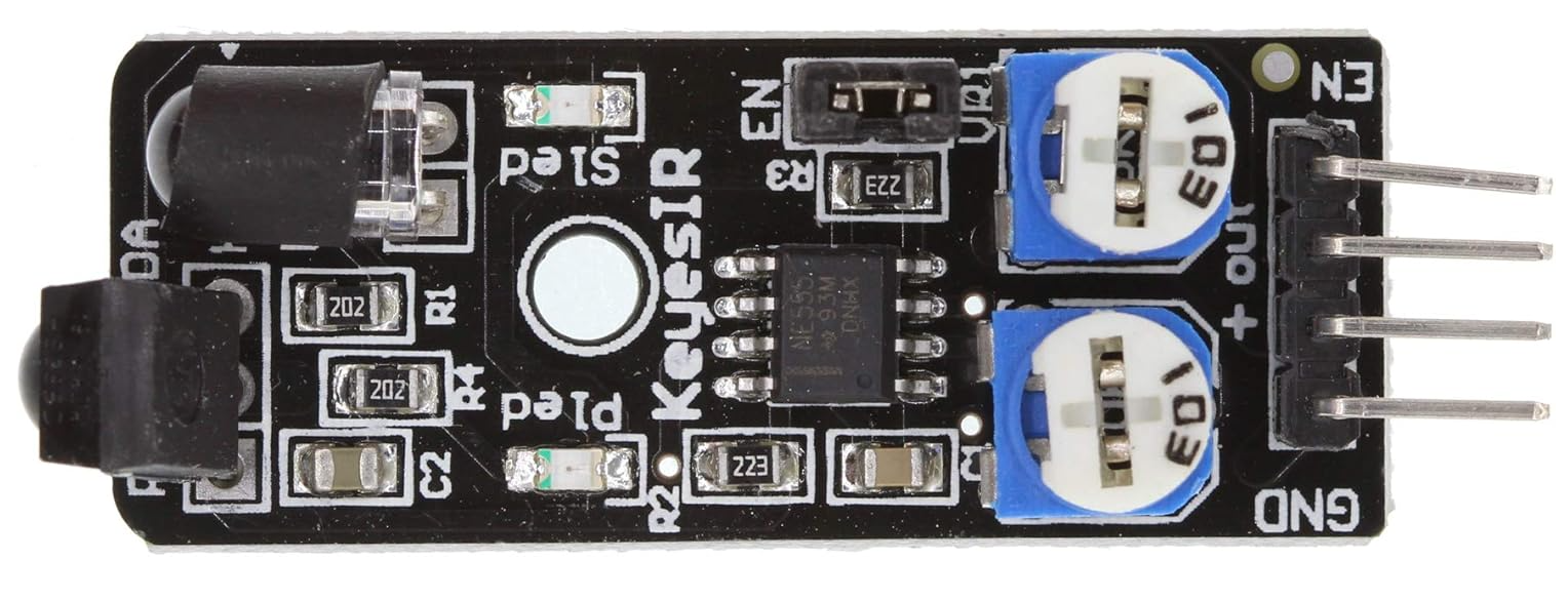
The KeyesIR KY-032 is an infrared (IR) sensor module designed to detect infrared radiation. It is widely used in applications such as proximity sensing, motion detection, and remote control systems. The sensor operates by emitting infrared light and detecting the reflected signal, making it ideal for obstacle detection and line-following robots.
This module is compact, easy to use, and compatible with microcontrollers like Arduino, Raspberry Pi, and other development boards. Its adjustable sensitivity and range make it versatile for a variety of projects.
Explore Projects Built with IR Sensor
Explore Projects Built with IR Sensor
Technical Specifications
Below are the key technical details of the KeyesIR KY-032 IR sensor module:
| Parameter | Specification |
|---|---|
| Operating Voltage | 3.3V - 5V DC |
| Operating Current | ≤ 20mA |
| Detection Range | 2cm - 30cm (adjustable) |
| Detection Angle | 35° |
| Output Type | Digital (High/Low) |
| Sensitivity Adjustment | Potentiometer |
| Dimensions | 3.1cm x 1.5cm x 0.7cm |
Pin Configuration and Descriptions
The KY-032 IR sensor module has four pins, as described in the table below:
| Pin | Name | Description |
|---|---|---|
| 1 | VCC | Power supply pin. Connect to 3.3V or 5V DC. |
| 2 | GND | Ground pin. Connect to the ground of the circuit. |
| 3 | OUT | Digital output pin. Outputs HIGH (1) when no obstacle is detected, LOW (0) when an obstacle is detected. |
| 4 | EN | Enable pin. Used to enable or disable the sensor (optional, usually connected to VCC). |
Usage Instructions
How to Use the KY-032 IR Sensor in a Circuit
- Power the Sensor: Connect the VCC pin to a 3.3V or 5V power source and the GND pin to the ground.
- Connect the Output: Connect the OUT pin to a digital input pin on your microcontroller or development board.
- Adjust Sensitivity: Use the onboard potentiometer to adjust the detection range and sensitivity of the sensor.
- Enable the Sensor: If using the EN pin, connect it to VCC to enable the sensor. If not used, leave it connected to VCC by default.
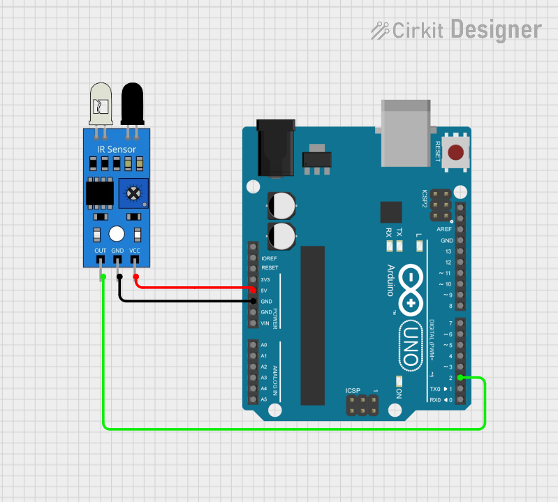
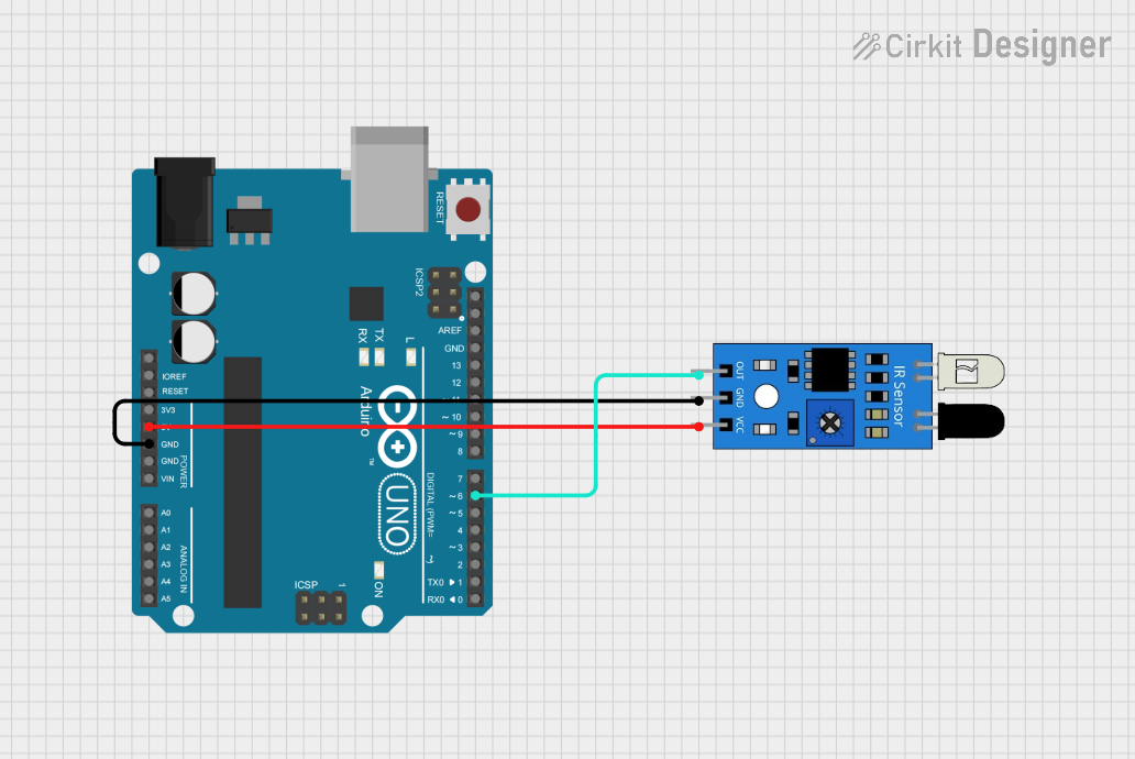
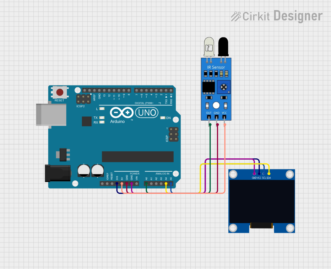
Example Circuit with Arduino UNO
Below is an example of how to connect the KY-032 IR sensor to an Arduino UNO:
| KY-032 Pin | Arduino UNO Pin |
|---|---|
| VCC | 5V |
| GND | GND |
| OUT | Digital Pin 2 |
| EN | 5V |
Example Arduino Code
The following code demonstrates how to use the KY-032 IR sensor with an Arduino UNO to detect obstacles:
// Define the pin connected to the KY-032 OUT pin
const int irSensorPin = 2;

// Variable to store the sensor state
int sensorState = 0;

void setup() {
  // Initialize the serial monitor for debugging
  Serial.begin(9600);

  // Set the IR sensor pin as input
  pinMode(irSensorPin, INPUT);
}

void loop() {
  // Read the state of the IR sensor
  sensorState = digitalRead(irSensorPin);

  // Check if an obstacle is detected
  if (sensorState == LOW) {
    Serial.println("Obstacle detected!"); // Print message if obstacle is detected
  } else {
    Serial.println("No obstacle detected."); // Print message if no obstacle is detected
  }

  // Add a small delay to avoid flooding the serial monitor
  delay(200);
}
Important Considerations and Best Practices
- Power Supply: Ensure the sensor is powered within its operating voltage range (3.3V - 5V).
- Ambient Light: Avoid using the sensor in environments with strong ambient IR light (e.g., direct sunlight), as it may affect performance.
- Sensitivity Adjustment: Use the onboard potentiometer to fine-tune the detection range for your specific application.
- Mounting: Position the sensor at an appropriate angle and distance for optimal detection.
Troubleshooting and FAQs
Common Issues and Solutions
Sensor Not Detecting Obstacles:
- Ensure the sensor is powered correctly (check VCC and GND connections).
- Adjust the sensitivity using the potentiometer.
- Verify that the obstacle is within the detection range (2cm - 30cm).
False Positives or Erratic Behavior:
- Check for interference from ambient IR sources (e.g., sunlight, other IR devices).
- Ensure stable power supply voltage to the sensor.
No Output Signal:
- Verify the OUT pin connection to the microcontroller.
- Check if the EN pin is connected to VCC to enable the sensor.
FAQs
Q1: Can the KY-032 IR sensor detect transparent objects?
A1: No, the sensor may not reliably detect transparent or highly reflective objects due to the way infrared light is reflected.
Q2: How do I increase the detection range?
A2: Use the onboard potentiometer to adjust the sensitivity. Note that increasing the range may reduce accuracy.
Q3: Can I use the KY-032 with a 3.3V microcontroller?
A3: Yes, the sensor operates at both 3.3V and 5V, making it compatible with 3.3V microcontrollers like ESP32 or Raspberry Pi.
Q4: What is the purpose of the EN pin?
A4: The EN pin is used to enable or disable the sensor. If not used, it should be connected to VCC by default.