
How to Use TRANSISTOR_NPN_2: Examples, Pinouts, and Specs

 Design with TRANSISTOR_NPN_2 in Cirkit Designer
Introduction
The TRANSISTOR_NPN_2 is a type of bipolar junction transistor (BJT) that utilizes both electron and hole charge carriers for operation. It is designed to amplify or switch electronic signals, making it a versatile component in various electronic circuits. This NPN transistor is widely used in applications where a small input current is required to control a larger output current. Its reliability and efficiency make it a popular choice for hobbyists and professionals alike.
Explore Projects Built with TRANSISTOR_NPN_2
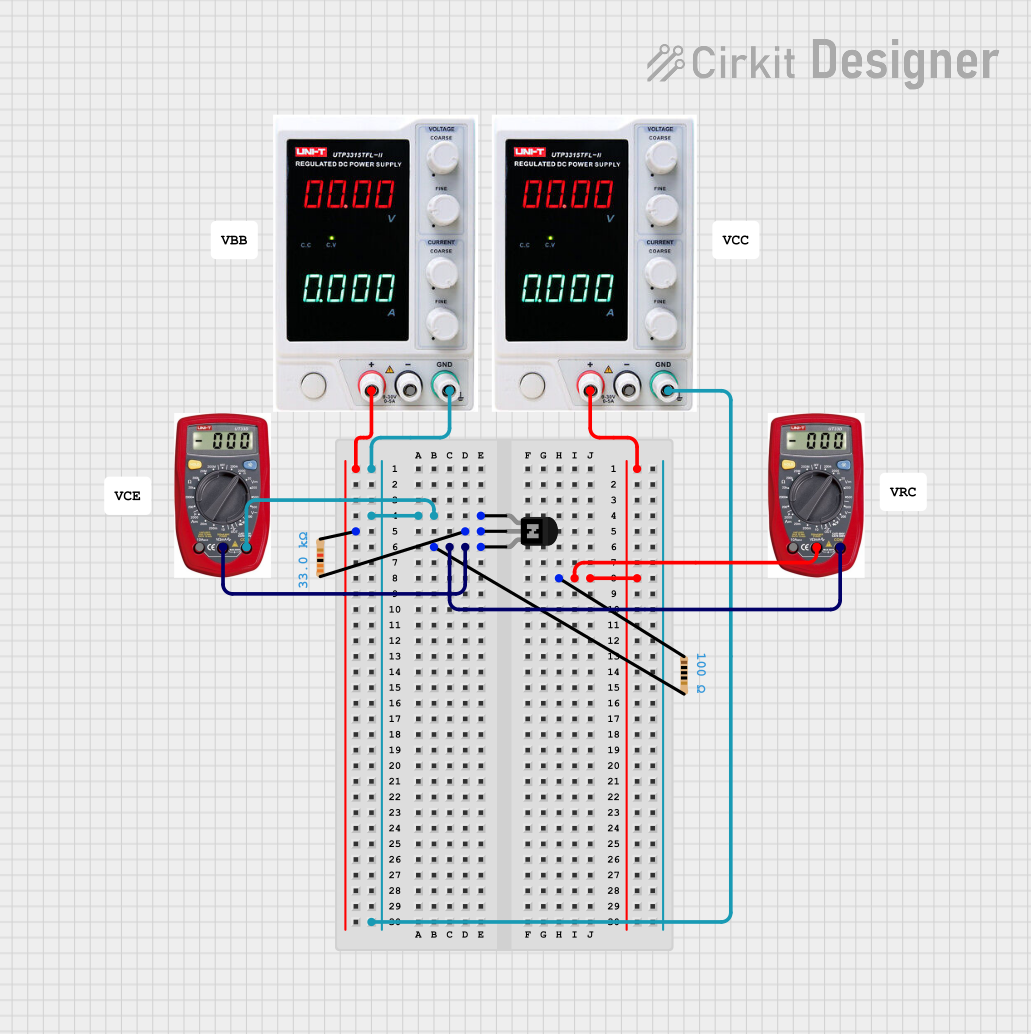 Open Project in Cirkit Designer
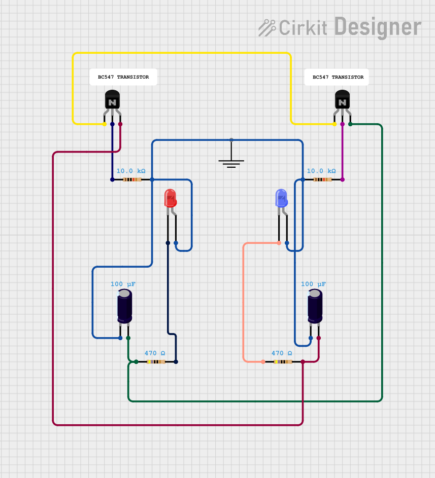 Open Project in Cirkit Designer
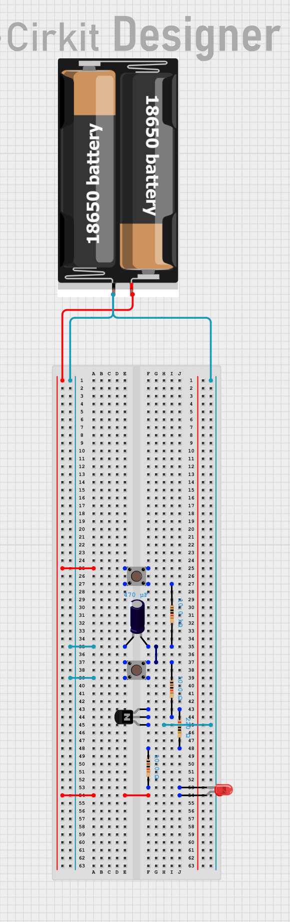 Open Project in Cirkit Designer
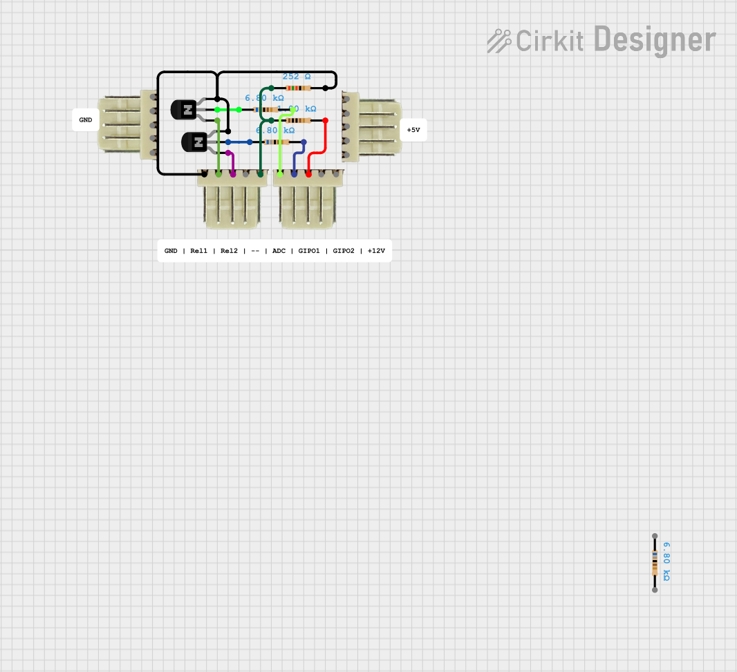 Open Project in Cirkit Designer
Explore Projects Built with TRANSISTOR_NPN_2
Open Project in Cirkit DesignerOpen Project in Cirkit DesignerOpen Project in Cirkit DesignerOpen Project in Cirkit DesignerCommon Applications:
- Signal amplification in audio and RF circuits
- Switching applications in digital circuits
- Motor control and driving relays
- LED and other load control in microcontroller-based systems
Technical Specifications
Key Specifications:
| Parameter | Value |
|---|---|
| Transistor Type | NPN |
| Maximum Collector-Emitter Voltage (VCE) | 40V |
| Maximum Collector Current (IC) | 800mA |
| Maximum Base Current (IB) | 200mA |
| DC Current Gain (hFE) | 100 - 300 |
| Power Dissipation (PD) | 500mW |
| Transition Frequency (fT) | 150 MHz |
| Operating Temperature Range | -55°C to +150°C |
| Package Type | TO-92 |
Pin Configuration:
The TRANSISTOR_NPN_2 has three pins, as shown in the table below:
| Pin Number | Pin Name | Description |
|---|---|---|
| 1 | Collector | Current flows out of this terminal. |
| 2 | Base | Controls the transistor's operation. |
| 3 | Emitter | Current flows into this terminal. |
Usage Instructions
How to Use the TRANSISTOR_NPN_2 in a Circuit:
- Identify the Pins: Refer to the pin configuration table to correctly identify the collector, base, and emitter pins.
- Connect the Base Resistor: To prevent damage to the transistor, always use a resistor in series with the base pin. Calculate the resistor value using Ohm's Law:
[ R_B = \frac{V_{in} - V_{BE}}{I_B} ]
where ( V_{BE} ) is typically 0.7V for an NPN transistor. - Set Up the Circuit:
- Connect the emitter to ground.
- Connect the load (e.g., LED, motor) between the collector and the positive voltage supply.
- Apply a small current to the base to control the larger current flowing from the collector to the emitter.
- Test the Circuit: Power the circuit and verify the operation. Adjust the base current as needed to achieve the desired output.
Important Considerations:
- Base Current Limitation: Ensure the base current does not exceed the maximum rating (200mA) to avoid damaging the transistor.
- Heat Dissipation: If the transistor operates near its maximum power dissipation, consider using a heatsink.
- Voltage Ratings: Do not exceed the maximum collector-emitter voltage (40V) to prevent breakdown.
Example: Controlling an LED with Arduino UNO
Below is an example of using the TRANSISTOR_NPN_2 to control an LED with an Arduino UNO:
// Define the pin connected to the transistor's base
const int basePin = 9; // Digital pin 9 on Arduino

void setup() {
  pinMode(basePin, OUTPUT); // Set the base pin as an output
}

void loop() {
  digitalWrite(basePin, HIGH); // Turn on the transistor (LED ON)
  delay(1000);                 // Wait for 1 second
  digitalWrite(basePin, LOW);  // Turn off the transistor (LED OFF)
  delay(1000);                 // Wait for 1 second
}
Circuit Connections:
- Connect the emitter to ground.
- Connect the collector to one terminal of the LED. The other terminal of the LED should connect to a current-limiting resistor, which is then connected to the positive voltage supply.
- Connect the base to the Arduino's digital pin (e.g., pin 9) through a 1kΩ resistor.
Troubleshooting and FAQs
Common Issues:
Transistor Not Switching:
- Cause: Insufficient base current.
- Solution: Check the base resistor value and ensure the base current is adequate to drive the load.
Overheating:
- Cause: Exceeding the maximum power dissipation or improper heat management.
- Solution: Reduce the load current or use a heatsink to dissipate heat.
No Output Current:
- Cause: Incorrect pin connections.
- Solution: Double-check the pin configuration and ensure proper wiring.
LED Not Lighting Up:
- Cause: Incorrect resistor value or damaged LED.
- Solution: Verify the LED and resistor values. Replace components if necessary.
FAQs:
Q1: Can I use the TRANSISTOR_NPN_2 for high-frequency applications?
A1: Yes, the TRANSISTOR_NPN_2 has a transition frequency of 150 MHz, making it suitable for high-frequency applications.
Q2: What happens if I exceed the maximum collector current?
A2: Exceeding the maximum collector current (800mA) can damage the transistor permanently. Always ensure the load current is within the specified limits.
Q3: Can I use this transistor without a base resistor?
A3: No, a base resistor is essential to limit the base current and protect the transistor from damage.
By following this documentation, you can effectively use the TRANSISTOR_NPN_2 in your electronic projects for amplification and switching purposes.