How to Use POWER SUPPLY 24V: Examples, Pinouts, and Specs
Introduction
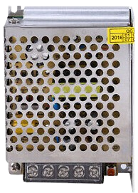
The POWER SUPPLY 24V is a device designed to convert electrical energy from an input source (such as AC mains or DC power) into a stable 24V DC output. This regulated output is ideal for powering a wide range of electronic circuits, industrial equipment, and automation systems. Its reliability and efficiency make it a critical component in applications requiring consistent voltage levels.
Explore Projects Built with POWER SUPPLY 24V


Explore Projects Built with POWER SUPPLY 24V
Common Applications and Use Cases
- Industrial automation systems
- Robotics and motor controllers
- LED lighting systems
- Laboratory equipment
- Powering microcontrollers and sensors
- Telecommunications and networking devices
Technical Specifications
Below are the key technical details for the POWER SUPPLY 24V:
| Parameter | Value |
|---|---|
| Input Voltage Range | 100-240V AC (50/60Hz) or 12-48V DC |
| Output Voltage | 24V DC |
| Output Current | 1A to 10A (varies by model) |
| Power Rating | 24W to 240W (varies by model) |
| Efficiency | Up to 90% |
| Ripple and Noise | < 50mV |
| Operating Temperature | -20°C to +70°C |
| Protection Features | Overvoltage, Overcurrent, Short Circuit |
| Dimensions | Varies by model (e.g., 100mm x 50mm x 30mm) |
| Mounting Options | DIN rail, panel mount, or standalone |
Pin Configuration and Descriptions
The POWER SUPPLY 24V typically has the following input and output terminals:
| Pin/Terminal | Label | Description |
|---|---|---|
| 1 | L | Live AC input (for AC-powered models) |
| 2 | N | Neutral AC input (for AC-powered models) |
| 3 | GND | Ground connection (optional for safety) |
| 4 | +V OUT | Positive 24V DC output |
| 5 | -V OUT | Negative (ground) 24V DC output |
For DC-powered models, the input terminals may be labeled as +VIN and -VIN instead of L and N.
Usage Instructions
How to Use the POWER SUPPLY 24V in a Circuit
- Verify Input Voltage: Ensure the input voltage matches the specifications of the power supply (e.g., 100-240V AC or 12-48V DC).
- Connect Input Terminals:
- For AC-powered models, connect the live wire to the
Lterminal and the neutral wire to theNterminal. - For DC-powered models, connect the positive input to
+VINand the negative input to-VIN.
- For AC-powered models, connect the live wire to the
- Connect Output Terminals:
- Connect the
+V OUTterminal to the positive rail of your circuit. - Connect the
-V OUTterminal to the ground rail of your circuit.
- Connect the
- Power On: Switch on the input power source and verify the output voltage using a multimeter.
- Load Connection: Connect your load (e.g., motor, microcontroller, or LED) to the output terminals.
Important Considerations and Best Practices
- Load Capacity: Ensure the total current draw of your load does not exceed the maximum output current rating of the power supply.
- Ventilation: Install the power supply in a well-ventilated area to prevent overheating.
- Safety: Use proper insulation and grounding to avoid electrical hazards.
- Ripple Sensitivity: If your circuit is sensitive to noise, consider adding additional filtering capacitors to the output.
- Arduino Compatibility: The 24V output is not directly compatible with Arduino boards, which typically operate at 5V or 3.3V. Use a step-down voltage regulator (e.g., LM2596) to safely power an Arduino from the 24V supply.
Example: Using a POWER SUPPLY 24V with an Arduino UNO
To power an Arduino UNO from a 24V power supply, you can use a step-down voltage regulator to convert 24V to 5V. Below is an example circuit and Arduino code:
Circuit Setup:
- Connect the
+V OUTterminal of the power supply to the input of the step-down regulator. - Set the regulator output to 5V using a multimeter.
- Connect the regulator's 5V output to the Arduino's
5Vpin and ground to the Arduino'sGNDpin.
Arduino Code:
// Example code to blink an LED connected to pin 13
void setup() {
  pinMode(13, OUTPUT); // Set pin 13 as an output
}

void loop() {
  digitalWrite(13, HIGH); // Turn the LED on
  delay(1000);            // Wait for 1 second
  digitalWrite(13, LOW);  // Turn the LED off
  delay(1000);            // Wait for 1 second
}
Troubleshooting and FAQs
Common Issues and Solutions
No Output Voltage:
- Cause: Input power is not connected or is outside the specified range.
- Solution: Verify the input voltage and connections.
Overheating:
- Cause: Insufficient ventilation or excessive load.
- Solution: Ensure proper airflow and reduce the load to within the rated current.
Output Voltage Fluctuations:
- Cause: High ripple or noise on the input power.
- Solution: Add filtering capacitors or use a power conditioner.
Load Not Powering On:
- Cause: Incorrect wiring or insufficient current capacity.
- Solution: Double-check connections and ensure the load's current draw is within the power supply's limits.
FAQs
Q1: Can I use the POWER SUPPLY 24V to charge a 24V battery?
A1: Yes, but ensure the power supply has a current-limiting feature or use an external charge controller to prevent overcharging.
Q2: Is the POWER SUPPLY 24V waterproof?
A2: Most models are not waterproof. Use an enclosure for outdoor or wet environments.
Q3: Can I connect multiple power supplies in parallel for higher current?
A3: Only if the power supplies are designed for parallel operation. Check the manufacturer's specifications.
Q4: What happens if I connect a 12V device to the 24V output?
A4: The device may be damaged due to overvoltage. Use a step-down regulator to safely power 12V devices.