
How to Use WRIST MPU6050 - HAND TREMOR: Examples, Pinouts, and Specs
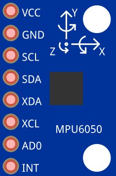
 Design with WRIST MPU6050 - HAND TREMOR in Cirkit Designer
Introduction
The WRIST MPU6050, manufactured by InvenSense (Part ID: MPU-6050), is a motion tracking device that integrates a 3-axis gyroscope and a 3-axis accelerometer into a single chip. This component is widely used for detecting hand tremors and monitoring movement, making it ideal for applications in health monitoring, rehabilitation, and wearable devices. Its compact design and high precision make it a popular choice for motion tracking in medical and consumer electronics.
Explore Projects Built with WRIST MPU6050 - HAND TREMOR
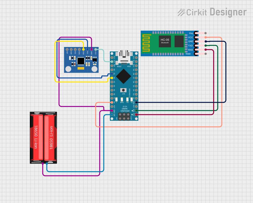 Open Project in Cirkit Designer
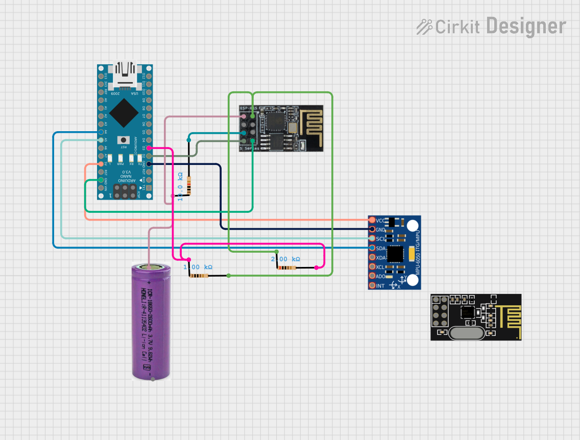 Open Project in Cirkit Designer
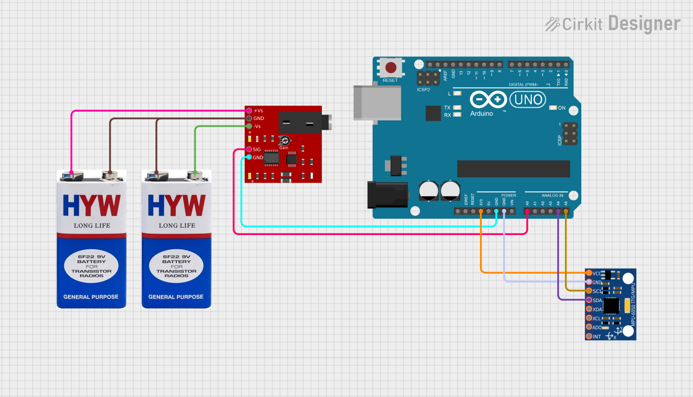 Open Project in Cirkit Designer
 Open Project in Cirkit Designer
Explore Projects Built with WRIST MPU6050 - HAND TREMOR
Open Project in Cirkit DesignerOpen Project in Cirkit DesignerOpen Project in Cirkit DesignerOpen Project in Cirkit DesignerCommon Applications and Use Cases
- Monitoring hand tremors in patients with Parkinson's disease or other neurological disorders.
- Rehabilitation devices for tracking hand movement and recovery progress.
- Wearable devices for motion analysis and gesture recognition.
- Gaming controllers and virtual reality systems for motion tracking.
- Robotics and drone stabilization systems.
Technical Specifications
The WRIST MPU6050 offers the following key technical details:
| Parameter | Value |
|---|---|
| Manufacturer | InvenSense |
| Part ID | MPU-6050 |
| Supply Voltage (VDD) | 2.375V to 3.46V |
| Logic Voltage (VDDIO) | 1.8V to VDD |
| Gyroscope Range | ±250, ±500, ±1000, ±2000 degrees/second |
| Accelerometer Range | ±2g, ±4g, ±8g, ±16g |
| Communication Interface | I2C (up to 400kHz) or SPI (up to 1MHz) |
| Operating Temperature | -40°C to +85°C |
| Package Type | 24-pin QFN (4x4x0.9mm) |
Pin Configuration and Descriptions
The MPU-6050 has 24 pins, but the most commonly used pins for basic operation are listed below:
| Pin Name | Pin Number | Description |
|---|---|---|
| VDD | 1 | Power supply input (2.375V to 3.46V). |
| VDDIO | 2 | Logic voltage input (1.8V to VDD). |
| GND | 3 | Ground connection. |
| SCL | 6 | I2C clock input. |
| SDA | 7 | I2C data input/output. |
| INT | 12 | Interrupt signal output. |
| FSYNC | 14 | Frame synchronization input. |
| AD0 | 15 | I2C address select (0 or 1). |
| AUX_DA | 18 | Auxiliary I2C data line. |
| AUX_CL | 19 | Auxiliary I2C clock line. |
For a complete pinout, refer to the official datasheet provided by InvenSense.
Usage Instructions
How to Use the WRIST MPU6050 in a Circuit
- Power Supply: Connect the VDD pin to a 3.3V power source and the GND pin to ground. Ensure the logic voltage (VDDIO) matches the microcontroller's I/O voltage level.
- I2C Communication: Connect the SCL and SDA pins to the corresponding I2C pins on your microcontroller. Use pull-up resistors (typically 4.7kΩ) on both lines.
- Interrupt Pin: Optionally, connect the INT pin to a digital input pin on your microcontroller to handle interrupts.
- Address Selection: Use the AD0 pin to set the I2C address. Connect it to GND for address
0x68or to VDD for address0x69.
Important Considerations and Best Practices
- Bypass Capacitors: Place a 0.1µF ceramic capacitor close to the VDD pin to stabilize the power supply.
- Mounting Orientation: Ensure the MPU6050 is mounted securely and aligned correctly for accurate motion tracking.
- Calibration: Perform gyroscope and accelerometer calibration to improve accuracy.
- Noise Filtering: Use the built-in Digital Motion Processor (DMP) to filter noise and process motion data.
Example Code for Arduino UNO
Below is an example of how to interface the WRIST MPU6050 with an Arduino UNO using the I2C protocol:
#include <Wire.h>

// MPU6050 I2C address (default is 0x68 when AD0 is connected to GND)
const int MPU6050_ADDR = 0x68;

// Registers for accelerometer and gyroscope data
const int ACCEL_XOUT_H = 0x3B;
const int GYRO_XOUT_H = 0x43;

void setup() {
  Wire.begin(); // Initialize I2C communication
  Serial.begin(9600); // Start serial communication for debugging

  // Wake up the MPU6050 (set power management register to 0)
  Wire.beginTransmission(MPU6050_ADDR);
  Wire.write(0x6B); // Power management register
  Wire.write(0);    // Set to 0 to wake up the sensor
  Wire.endTransmission();
}

void loop() {
  int16_t accelX, accelY, accelZ;
  int16_t gyroX, gyroY, gyroZ;

  // Read accelerometer data
  accelX = readMPU6050(ACCEL_XOUT_H);
  accelY = readMPU6050(ACCEL_XOUT_H + 2);
  accelZ = readMPU6050(ACCEL_XOUT_H + 4);

  // Read gyroscope data
  gyroX = readMPU6050(GYRO_XOUT_H);
  gyroY = readMPU6050(GYRO_XOUT_H + 2);
  gyroZ = readMPU6050(GYRO_XOUT_H + 4);

  // Print data to the serial monitor
  Serial.print("Accel: ");
  Serial.print(accelX); Serial.print(", ");
  Serial.print(accelY); Serial.print(", ");
  Serial.print(accelZ); Serial.print(" | Gyro: ");
  Serial.print(gyroX); Serial.print(", ");
  Serial.print(gyroY); Serial.print(", ");
  Serial.println(gyroZ);

  delay(500); // Delay for readability
}

// Function to read 16-bit data from MPU6050
int16_t readMPU6050(int reg) {
  Wire.beginTransmission(MPU6050_ADDR);
  Wire.write(reg); // Specify the register to read from
  Wire.endTransmission(false);
  Wire.requestFrom(MPU6050_ADDR, 2, true); // Request 2 bytes of data

  int16_t data = Wire.read() << 8 | Wire.read(); // Combine high and low bytes
  return data;
}
Troubleshooting and FAQs
Common Issues
No Data from MPU6050:
- Ensure the I2C connections (SCL and SDA) are correct and have pull-up resistors.
- Verify the I2C address (default is
0x68unless AD0 is connected to VDD).
Inaccurate Readings:
- Perform calibration for both the gyroscope and accelerometer.
- Check for vibrations or loose mounting that may affect measurements.
Device Not Detected:
- Confirm the power supply voltage is within the specified range.
- Use an I2C scanner sketch to detect the device address.
Tips for Troubleshooting
- Use a logic analyzer or oscilloscope to verify I2C communication.
- Check for proper grounding and stable power supply.
- Refer to the official datasheet for advanced configuration and troubleshooting.
By following this documentation, users can effectively integrate the WRIST MPU6050 into their projects for accurate motion tracking and hand tremor detection.