Cirkit Designer
Your all-in-one circuit design IDE
Home /
Component Documentation
How to Use RELAY: Examples, Pinouts, and Specs
Introduction
The RELAY KAKI 4 is an electrically operated switch manufactured by 12V. It is designed to control a circuit by a low-power signal or to control several circuits with a single signal. Relays are essential components in various applications, including home automation, industrial control systems, and automotive electronics.
Explore Projects Built with RELAY
WeMos D1 R2 Controlled Relay Switching Circuit for AC Bulb and USB Charger

This circuit uses a WeMos D1 R2 microcontroller to control a 5V 2-relay module, which in turn controls the power to an AC bulb and a cellphone charger. The microcontroller also interfaces with a line tracking sensor, which likely provides input to control the relay states. The AC bulb and cellphone charger are powered by an AC wire connection, with the relay acting as a switch for the bulb.
Battery-Powered IR Sensor Controlled Relay Module

This circuit uses an IR sensor to control a 1 Channel 5V Relay Module, which is powered by a 9V battery. The IR sensor detects an object and sends a signal to the relay module to switch its state, enabling or disabling the connected load.
ESP32-Controlled DC Motor with Dual Relay System

This circuit controls a DC motor using two 12V relays, which are powered by a 12V supply through a barrel jack. The relays are configured to switch the motor's connections, allowing for control over its operation.
Arduino UNO and SIM900A Based Smart Home Automation with GSM and I2C LCD Display
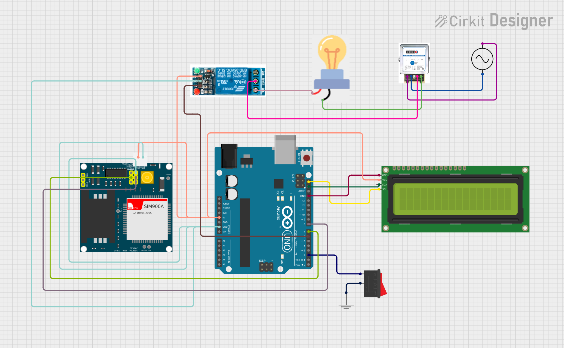
This circuit is a remote-controlled relay system using an Arduino UNO, a SIM900A GSM module, and a 5V relay to control a bulb. The Arduino communicates with the GSM module to receive commands, which are then used to toggle the relay, thereby controlling the bulb. Additionally, a 16x2 I2C LCD is used for displaying status information.
Explore Projects Built with RELAY
WeMos D1 R2 Controlled Relay Switching Circuit for AC Bulb and USB Charger
This circuit uses a WeMos D1 R2 microcontroller to control a 5V 2-relay module, which in turn controls the power to an AC bulb and a cellphone charger. The microcontroller also interfaces with a line tracking sensor, which likely provides input to control the relay states. The AC bulb and cellphone charger are powered by an AC wire connection, with the relay acting as a switch for the bulb.
Battery-Powered IR Sensor Controlled Relay Module
This circuit uses an IR sensor to control a 1 Channel 5V Relay Module, which is powered by a 9V battery. The IR sensor detects an object and sends a signal to the relay module to switch its state, enabling or disabling the connected load.
ESP32-Controlled DC Motor with Dual Relay System
This circuit controls a DC motor using two 12V relays, which are powered by a 12V supply through a barrel jack. The relays are configured to switch the motor's connections, allowing for control over its operation.
Arduino UNO and SIM900A Based Smart Home Automation with GSM and I2C LCD Display
This circuit is a remote-controlled relay system using an Arduino UNO, a SIM900A GSM module, and a 5V relay to control a bulb. The Arduino communicates with the GSM module to receive commands, which are then used to toggle the relay, thereby controlling the bulb. Additionally, a 16x2 I2C LCD is used for displaying status information.
Common Applications and Use Cases
- Home Automation: Used to control lights, fans, and other household appliances.
- Industrial Control Systems: Employed in machinery to control high-power devices.
- Automotive Electronics: Utilized in vehicles to manage various electrical systems.
- Safety Systems: Implemented in alarm systems and emergency shutdown mechanisms.
Technical Specifications
Key Technical Details
| Parameter | Value |
|---|---|
| Operating Voltage | 12V DC |
| Coil Resistance | 400 Ohms |
| Contact Rating | 10A at 250V AC |
| Contact Type | SPDT (Single Pole Double Throw) |
| Switching Voltage | 250V AC / 30V DC |
| Switching Current | 10A |
| Operating Temperature | -40°C to 85°C |
| Dimensions | 28mm x 12mm x 15mm |
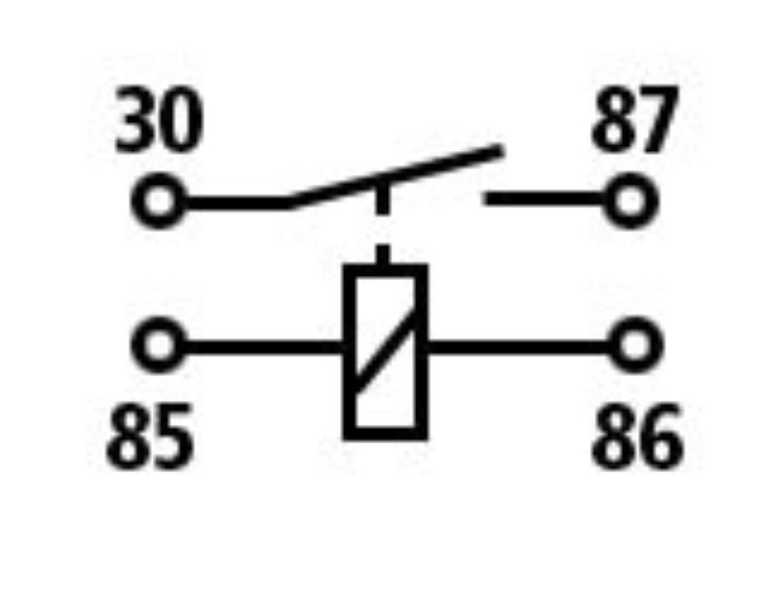
Pin Configuration and Descriptions
| Pin Number | Pin Name | Description |
|---|---|---|
| 1 | Coil+ | Positive terminal of the relay coil |
| 2 | Coil- | Negative terminal of the relay coil |
| 3 | COM | Common terminal |
| 4 | NO | Normally Open contact |
| 5 | NC | Normally Closed contact |
Usage Instructions
How to Use the Component in a Circuit
Power the Relay Coil:
- Connect the Coil+ pin to a 12V DC power source.
- Connect the Coil- pin to the ground.
Control the Load:
- Connect the load to the COM pin.
- Connect the other end of the load to either the NO or NC pin, depending on the desired operation:
- NO (Normally Open): The load is off when the relay is not energized and on when the relay is energized.
- NC (Normally Closed): The load is on when the relay is not energized and off when the relay is energized.
Control Signal:
- Use a low-power control signal (e.g., from a microcontroller) to energize the relay coil.
Important Considerations and Best Practices
- Diode Protection: Place a flyback diode across the relay coil to protect against voltage spikes.
- Current Rating: Ensure the load current does not exceed the relay's contact rating.
- Isolation: Use optocouplers for additional isolation between the control signal and the relay.
Example Circuit with Arduino UNO
/*
 * Example code to control a RELAY KAKI 4 with an Arduino UNO.
 * The relay is connected to pin 7 of the Arduino.
 */

const int relayPin = 7; // Pin connected to the relay

void setup() {
  pinMode(relayPin, OUTPUT); // Set the relay pin as an output
}

void loop() {
  digitalWrite(relayPin, HIGH); // Turn the relay on
  delay(1000); // Wait for 1 second
  digitalWrite(relayPin, LOW); // Turn the relay off
  delay(1000); // Wait for 1 second
}
Troubleshooting and FAQs
Common Issues Users Might Face
Relay Not Switching:
- Cause: Insufficient voltage or current to the relay coil.
- Solution: Ensure the power supply provides 12V DC and sufficient current.
Load Not Responding:
- Cause: Incorrect wiring of the load to the relay contacts.
- Solution: Verify the load is connected to the correct COM and NO/NC pins.
Relay Chattering:
- Cause: Unstable control signal or insufficient power supply.
- Solution: Stabilize the control signal and ensure a stable power supply.
Solutions and Tips for Troubleshooting
- Check Connections: Ensure all connections are secure and correct.
- Use a Multimeter: Measure voltages and continuity to diagnose issues.
- Consult Datasheets: Refer to the relay's datasheet for detailed specifications and guidelines.
By following this documentation, users can effectively integrate the RELAY KAKI 4 into their projects, ensuring reliable and efficient operation.