Cirkit Designer Logo
Cirkit Designer
Your all-in-one circuit design IDE
Home / 
Component Documentation

How to Use Membrane Switch: Examples, Pinouts, and Specs

Image of Membrane Switch
Cirkit Designer LogoDesign with Membrane Switch in Cirkit Designer

Introduction

A membrane switch is a type of electrical switch that consists of a thin, flexible membrane that can be pressed to complete a circuit. It is widely used in devices such as keyboards, control panels, and household appliances due to its low profile, lightweight design, and durability. Membrane switches are ideal for applications requiring a compact and cost-effective interface for user input.

Explore Projects Built with Membrane Switch

Use Cirkit Designer to design, explore, and prototype these projects online. Some projects support real-time simulation. Click "Open Project" to start designing instantly!
Wi-Fi Controlled Access System with ESP32, RFID, and Keypad
Image of Insight Automata Iot device: A project utilizing Membrane Switch in a practical application
This circuit is an IoT-based access control and monitoring system using an ESP32 microcontroller. It integrates an RFID reader, a membrane keypad, multiple pushbuttons, an OLED display, and an SD card module to log and display user interactions and system status. The system connects to Wi-Fi for remote data upload and time synchronization.
Cirkit Designer LogoOpen Project in Cirkit Designer
ESP8266 and Arduino Mega 2560 Based Access Control System with Dual Authentication
Image of finaloutput: A project utilizing Membrane Switch in a practical application
This circuit features an ESP8266 NodeMCU microcontroller connected to a relay module, a fingerprint scanner, a GLCD display, and an Arduino Mega 2560 which interfaces with a 4x4 membrane matrix keypad. The relay controls a 12V solenoid lock powered by a 12V battery, and the toggle switch is used to manage power distribution or mode selection. The ESP8266 facilitates communication between the fingerprint scanner, GLCD, and potentially external networks, while the Arduino Mega processes keypad inputs and may handle additional control logic.
Cirkit Designer LogoOpen Project in Cirkit Designer
ESP32-Based Smart Access Control System with RFID, Keypad, and OLED Display
Image of Insight Automata Iot device: A project utilizing Membrane Switch in a practical application
This circuit is an ESP32-based system that integrates multiple input devices including a membrane keypad, pushbuttons, an RFID reader, and an SD card module for data logging. It also features an OLED display for visual feedback and a red LED indicator, making it suitable for applications requiring user interaction, data storage, and network connectivity.
Cirkit Designer LogoOpen Project in Cirkit Designer
Wi-Fi Controlled Access System with ESP32, Keypad, and LCD Display
Image of tryyyyy: A project utilizing Membrane Switch in a practical application
This circuit is a Wi-Fi-enabled access control system using an ESP32 microcontroller, a 4x4 membrane keypad, and a 20x4 I2C LCD. The system allows users to enter a password via the keypad, which is verified by the ESP32; if correct, it activates a relay and displays the status on the LCD, while also providing web-based configuration and time synchronization via NTP.
Cirkit Designer LogoOpen Project in Cirkit Designer

Explore Projects Built with Membrane Switch

Use Cirkit Designer to design, explore, and prototype these projects online. Some projects support real-time simulation. Click "Open Project" to start designing instantly!
Image of Insight Automata Iot device: A project utilizing Membrane Switch in a practical application
Wi-Fi Controlled Access System with ESP32, RFID, and Keypad
This circuit is an IoT-based access control and monitoring system using an ESP32 microcontroller. It integrates an RFID reader, a membrane keypad, multiple pushbuttons, an OLED display, and an SD card module to log and display user interactions and system status. The system connects to Wi-Fi for remote data upload and time synchronization.
Cirkit Designer LogoOpen Project in Cirkit Designer
Image of finaloutput: A project utilizing Membrane Switch in a practical application
ESP8266 and Arduino Mega 2560 Based Access Control System with Dual Authentication
This circuit features an ESP8266 NodeMCU microcontroller connected to a relay module, a fingerprint scanner, a GLCD display, and an Arduino Mega 2560 which interfaces with a 4x4 membrane matrix keypad. The relay controls a 12V solenoid lock powered by a 12V battery, and the toggle switch is used to manage power distribution or mode selection. The ESP8266 facilitates communication between the fingerprint scanner, GLCD, and potentially external networks, while the Arduino Mega processes keypad inputs and may handle additional control logic.
Cirkit Designer LogoOpen Project in Cirkit Designer
Image of Insight Automata Iot device: A project utilizing Membrane Switch in a practical application
ESP32-Based Smart Access Control System with RFID, Keypad, and OLED Display
This circuit is an ESP32-based system that integrates multiple input devices including a membrane keypad, pushbuttons, an RFID reader, and an SD card module for data logging. It also features an OLED display for visual feedback and a red LED indicator, making it suitable for applications requiring user interaction, data storage, and network connectivity.
Cirkit Designer LogoOpen Project in Cirkit Designer
Image of tryyyyy: A project utilizing Membrane Switch in a practical application
Wi-Fi Controlled Access System with ESP32, Keypad, and LCD Display
This circuit is a Wi-Fi-enabled access control system using an ESP32 microcontroller, a 4x4 membrane keypad, and a 20x4 I2C LCD. The system allows users to enter a password via the keypad, which is verified by the ESP32; if correct, it activates a relay and displays the status on the LCD, while also providing web-based configuration and time synchronization via NTP.
Cirkit Designer LogoOpen Project in Cirkit Designer

Common Applications:

  • Keyboards (e.g., computer keyboards, calculator keypads)
  • Control panels for industrial equipment
  • Consumer electronics (e.g., microwave ovens, washing machines)
  • Medical devices
  • Automotive dashboards

Technical Specifications

Key Technical Details:

  • Operating Voltage: Typically 3.3V to 5V
  • Current Rating: < 100mA
  • Contact Resistance: 10Ω to 500Ω (varies by design)
  • Insulation Resistance: > 100MΩ at 100V DC
  • Operating Temperature: -40°C to 70°C
  • Lifespan: Up to 1 million actuations per key
  • Material: Polyester or polycarbonate for the membrane layers
  • Actuation Force: 150g to 300g (typical)

Pin Configuration and Descriptions:

Membrane switches typically have a flexible ribbon cable with a connector that interfaces with a circuit. The number of pins depends on the number of keys or contacts in the switch matrix.

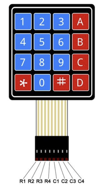
Example: 4x4 Membrane Keypad Pinout

Pin Number Description
1 Row 1 (R1)
2 Row 2 (R2)
3 Row 3 (R3)
4 Row 4 (R4)
5 Column 1 (C1)
6 Column 2 (C2)
7 Column 3 (C3)
8 Column 4 (C4)

The rows and columns form a matrix that allows the detection of key presses by scanning the rows and columns for connections.

Usage Instructions

How to Use the Membrane Switch in a Circuit:

  1. Connect the Ribbon Cable: Attach the ribbon cable from the membrane switch to a compatible connector or directly to a microcontroller using jumper wires.
  2. Matrix Scanning: Use a microcontroller to scan the rows and columns of the switch matrix to detect key presses.
  3. Pull-Up Resistors: If necessary, enable internal pull-up resistors on the microcontroller pins to ensure stable readings.
  4. Debouncing: Implement software debouncing to filter out noise caused by rapid key presses or releases.

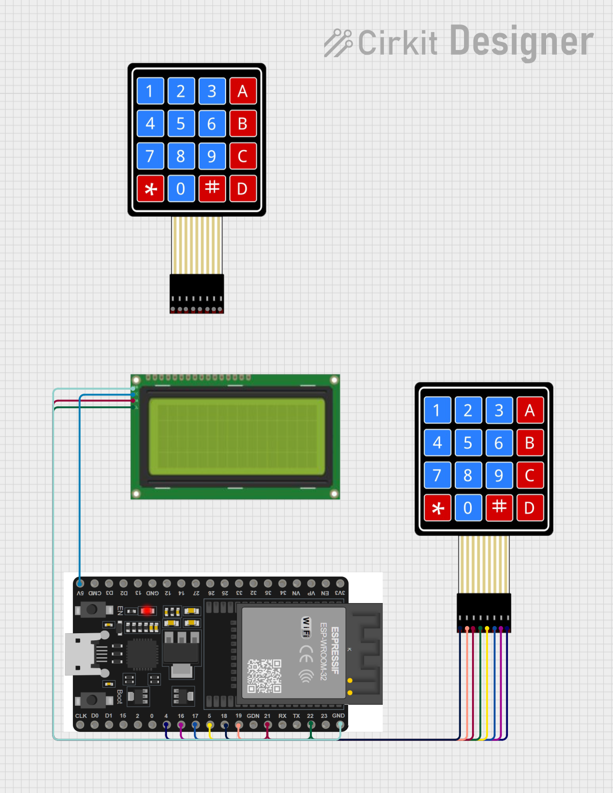
Example: Connecting a 4x4 Membrane Keypad to an Arduino UNO

Below is an example of how to connect and program a 4x4 membrane keypad with an Arduino UNO.

Circuit Diagram:

  • Connect the 8 pins of the keypad to digital pins 2 through 9 on the Arduino UNO.
  • Enable pull-up resistors in the code or use external resistors if needed.

Arduino Code:

#include <Keypad.h>

// Define the rows and columns of the keypad
const byte ROWS = 4; // Four rows
const byte COLS = 4; // Four columns

// Define the keymap for the 4x4 keypad
char keys[ROWS][COLS] = {
  {'1', '2', '3', 'A'},
  {'4', '5', '6', 'B'},
  {'7', '8', '9', 'C'},
  {'*', '0', '#', 'D'}
};

// Define the row and column pins connected to the Arduino
byte rowPins[ROWS] = {9, 8, 7, 6}; // Connect to R1, R2, R3, R4
byte colPins[COLS] = {5, 4, 3, 2}; // Connect to C1, C2, C3, C4

// Create a Keypad object
Keypad keypad = Keypad(makeKeymap(keys), rowPins, colPins, ROWS, COLS);

void setup() {
  Serial.begin(9600); // Initialize serial communication
  Serial.println("Membrane Keypad Test");
}

void loop() {
  char key = keypad.getKey(); // Check for key press

  if (key) {
    // Print the key pressed to the Serial Monitor
    Serial.print("Key Pressed: ");
    Serial.println(key);
  }
}

Important Considerations:

  • Voltage Levels: Ensure the operating voltage of the membrane switch matches the microcontroller's input voltage.
  • Debouncing: Without proper debouncing, key presses may register multiple times.
  • Connector Compatibility: Use a compatible connector or adapter for the ribbon cable to avoid damaging the switch.

Troubleshooting and FAQs

Common Issues:

  1. No Key Press Detected:

    • Cause: Loose or incorrect connections.
    • Solution: Verify the ribbon cable connections and ensure the pins are correctly mapped in the code.
  2. Multiple Keys Register Simultaneously:

    • Cause: Poor debouncing or electrical noise.
    • Solution: Implement software debouncing and check for proper grounding.
  3. Keys Not Responding:

    • Cause: Damaged membrane switch or incorrect pin configuration.
    • Solution: Test the switch with a multimeter to check for continuity and verify the pin configuration.
  4. Erratic Behavior:

    • Cause: Voltage fluctuations or missing pull-up resistors.
    • Solution: Use pull-up resistors and ensure a stable power supply.

FAQs:

Q1: Can I use a membrane switch with a Raspberry Pi?
A1: Yes, you can connect a membrane switch to a Raspberry Pi using GPIO pins. Use a library like gpiozero or RPi.GPIO to read the key presses.

Q2: How do I clean a membrane switch?
A2: Use a soft, lint-free cloth slightly dampened with isopropyl alcohol. Avoid using excessive moisture or abrasive materials.

Q3: What is the lifespan of a membrane switch?
A3: Most membrane switches are rated for up to 1 million actuations per key, depending on the manufacturer and usage conditions.

Q4: Can I customize the layout of a membrane switch?
A4: Yes, many manufacturers offer custom designs for membrane switches to suit specific applications.