How to Use 24C02 – 2 Kb I2C Serial EEPROM : Examples, Pinouts, and Specs
Introduction
The 24C02 is a 2 Kb I2C serial EEPROM (Electrically Erasable Programmable Read-Only Memory) manufactured by STMicroelectronics. It is designed for non-volatile data storage, meaning it retains data even when power is removed. The component communicates with microcontrollers and other devices using the I2C protocol, making it a versatile and easy-to-use memory solution for a wide range of applications.
Explore Projects Built with 24C02 – 2 Kb I2C Serial EEPROM


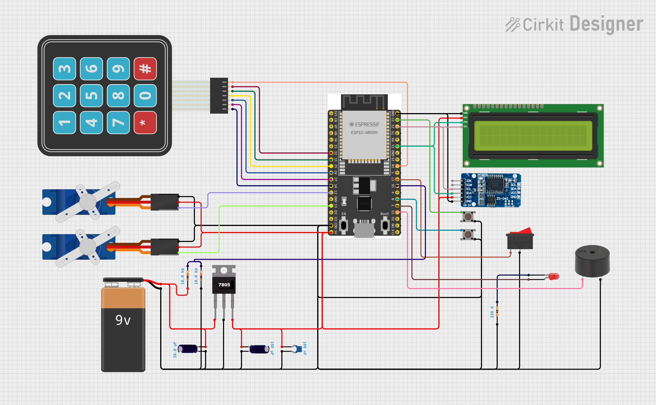
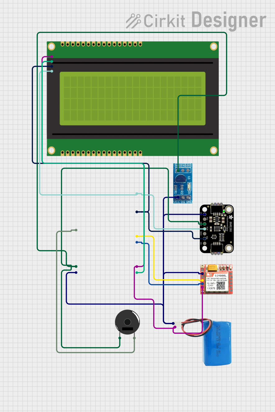
Explore Projects Built with 24C02 – 2 Kb I2C Serial EEPROM
Common Applications and Use Cases
- Storing configuration data for embedded systems
- Data logging in IoT devices
- Calibration data storage for sensors
- Non-volatile memory for microcontroller-based projects
- Storing user preferences in consumer electronics
Technical Specifications
The following are the key technical details of the 24C02 – 2 Kb I2C Serial EEPROM:
| Parameter | Value |
|---|---|
| Memory Size | 2 Kb (256 x 8 bits) |
| Interface Protocol | I2C (Inter-Integrated Circuit) |
| Operating Voltage Range | 1.8 V to 5.5 V |
| Maximum Clock Frequency | 400 kHz (Fast Mode) |
| Write Cycle Time | 5 ms (typical) |
| Data Retention | 40 years |
| Endurance | 1,000,000 write/erase cycles |
| Package Type | DIP-8 |
| Operating Temperature | -40°C to +85°C |
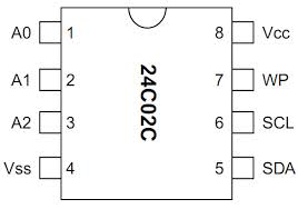
Pin Configuration and Descriptions
The 24C02 comes in an 8-pin DIP (Dual In-line Package) configuration. Below is the pinout and description:
| Pin Number | Pin Name | Description |
|---|---|---|
| 1 | A0 | Address input bit 0 (used for I2C slave address selection) |
| 2 | A1 | Address input bit 1 (used for I2C slave address selection) |
| 3 | A2 | Address input bit 2 (used for I2C slave address selection) |
| 4 | GND | Ground (0 V reference) |
| 5 | SDA | Serial Data Line (I2C bidirectional data line) |
| 6 | SCL | Serial Clock Line (I2C clock input) |
| 7 | WP | Write Protect (active HIGH; disables write operations when HIGH) |
| 8 | VCC | Power supply (1.8 V to 5.5 V) |
Usage Instructions
How to Use the 24C02 in a Circuit
- Power Supply: Connect the VCC pin to a power source (1.8 V to 5.5 V) and the GND pin to ground.
- I2C Connections:
- Connect the SDA pin to the microcontroller's I2C data line.
- Connect the SCL pin to the microcontroller's I2C clock line.
- Use pull-up resistors (typically 4.7 kΩ) on both the SDA and SCL lines.
- Address Selection: Use the A0, A1, and A2 pins to set the I2C slave address. These pins can be connected to either VCC (logic HIGH) or GND (logic LOW).
- Write Protection: If write protection is required, connect the WP pin to VCC. Leave it connected to GND or floating for normal read/write operations.
Important Considerations and Best Practices
- Pull-Up Resistors: Ensure proper pull-up resistors are used on the I2C lines to maintain signal integrity.
- Write Cycle Time: Allow sufficient time (5 ms) for write operations to complete before initiating another write.
- Address Conflicts: Avoid address conflicts when using multiple I2C devices on the same bus by configuring unique addresses using the A0, A1, and A2 pins.
- Decoupling Capacitor: Place a 0.1 µF decoupling capacitor close to the VCC pin to filter out noise.
Example Code for Arduino UNO
Below is an example of how to interface the 24C02 with an Arduino UNO to write and read data:
#include <Wire.h> // Include the Wire library for I2C communication

#define EEPROM_I2C_ADDRESS 0x50 // Base I2C address of 24C02 (A0, A1, A2 = GND)

void setup() {
  Wire.begin(); // Initialize I2C communication
  Serial.begin(9600); // Initialize serial communication for debugging

  // Write a byte to EEPROM
  writeEEPROM(0x00, 0x42); // Write 0x42 to memory address 0x00
  delay(10); // Wait for the write cycle to complete

  // Read the byte back from EEPROM
  byte data = readEEPROM(0x00);
  Serial.print("Read data: 0x");
  Serial.println(data, HEX); // Print the read data in hexadecimal format
}

void loop() {
  // Nothing to do here
}

// Function to write a byte to the 24C02 EEPROM
void writeEEPROM(byte address, byte data) {
  Wire.beginTransmission(EEPROM_I2C_ADDRESS); // Start I2C communication
  Wire.write(address); // Send memory address
  Wire.write(data); // Send data byte
  Wire.endTransmission(); // End I2C communication
}

// Function to read a byte from the 24C02 EEPROM
byte readEEPROM(byte address) {
  Wire.beginTransmission(EEPROM_I2C_ADDRESS); // Start I2C communication
  Wire.write(address); // Send memory address
  Wire.endTransmission(); // End transmission to set the address

  Wire.requestFrom(EEPROM_I2C_ADDRESS, 1); // Request 1 byte from EEPROM
  if (Wire.available()) {
    return Wire.read(); // Read and return the byte
  }
  return 0xFF; // Return 0xFF if no data is available
}
Troubleshooting and FAQs
Common Issues and Solutions
EEPROM Not Responding on I2C Bus:
- Cause: Incorrect I2C address or wiring.
- Solution: Verify the I2C address based on the A0, A1, and A2 pin configuration. Check the connections for SDA and SCL.
Data Not Written to EEPROM:
- Cause: Write protection is enabled.
- Solution: Ensure the WP pin is connected to GND or left floating for write operations.
Corrupted Data:
- Cause: Insufficient delay after a write operation.
- Solution: Add a delay of at least 5 ms after each write operation.
I2C Communication Errors:
- Cause: Missing or incorrect pull-up resistors.
- Solution: Use 4.7 kΩ pull-up resistors on the SDA and SCL lines.
FAQs
Q: Can I use the 24C02 with a 3.3 V microcontroller?
A: Yes, the 24C02 operates within a voltage range of 1.8 V to 5.5 V, making it compatible with 3.3 V systems.Q: How many 24C02 devices can I connect on the same I2C bus?
A: Up to 8 devices can be connected by configuring unique addresses using the A0, A1, and A2 pins.Q: What happens if the power is lost during a write operation?
A: The data being written may be corrupted. Ensure a stable power supply during write operations.Q: Can I read from the EEPROM while writing?
A: No, the EEPROM is busy during a write cycle and will not respond to read requests.
This concludes the documentation for the 24C02 – 2 Kb I2C Serial EEPROM.