How to Use L293D Driver Shield: Examples, Pinouts, and Specs
Introduction
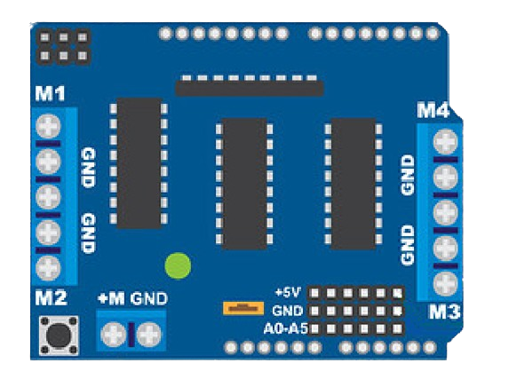
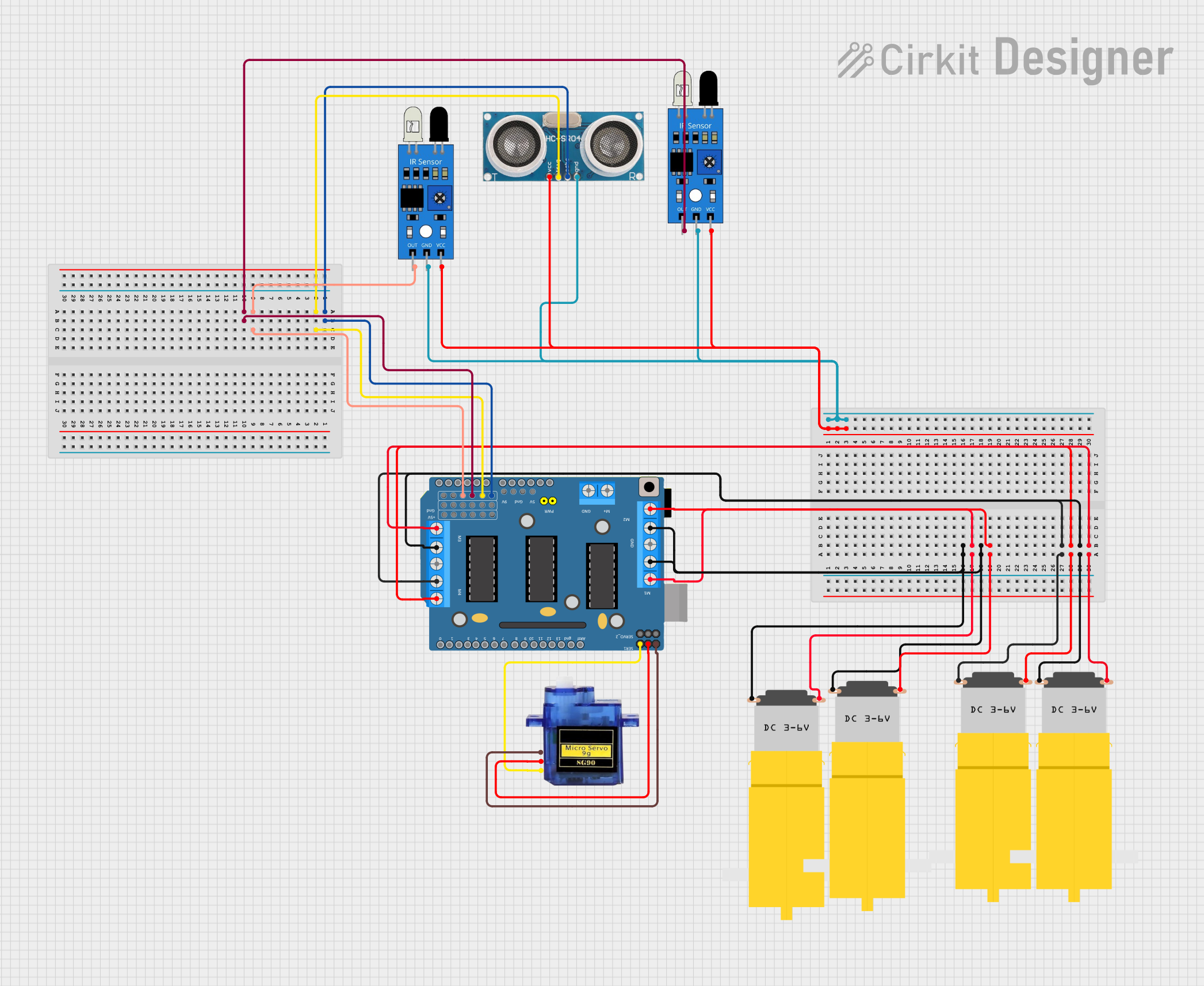
The L293D Driver Shield is an expansion board designed to facilitate the control of motors in robotics and automation projects. It is compatible with the Arduino UNO and other microcontroller boards, providing an easy-to-use interface for driving up to two DC motors or one stepper motor. The shield is based on the L293D motor driver IC, which can handle high current loads and is equipped with internal diodes for back EMF protection.
Explore Projects Built with L293D Driver Shield
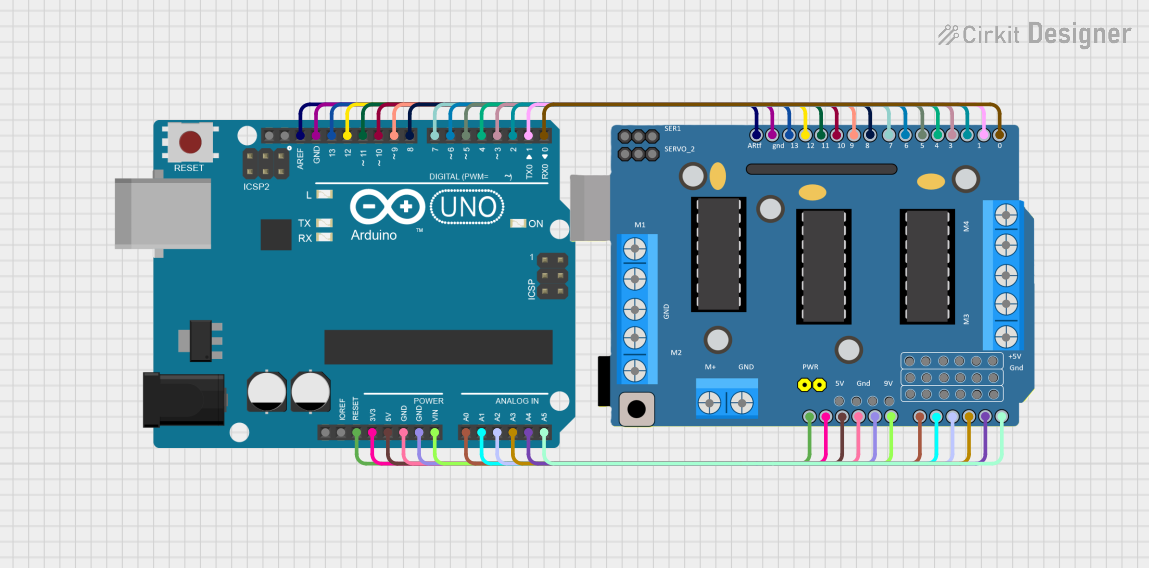
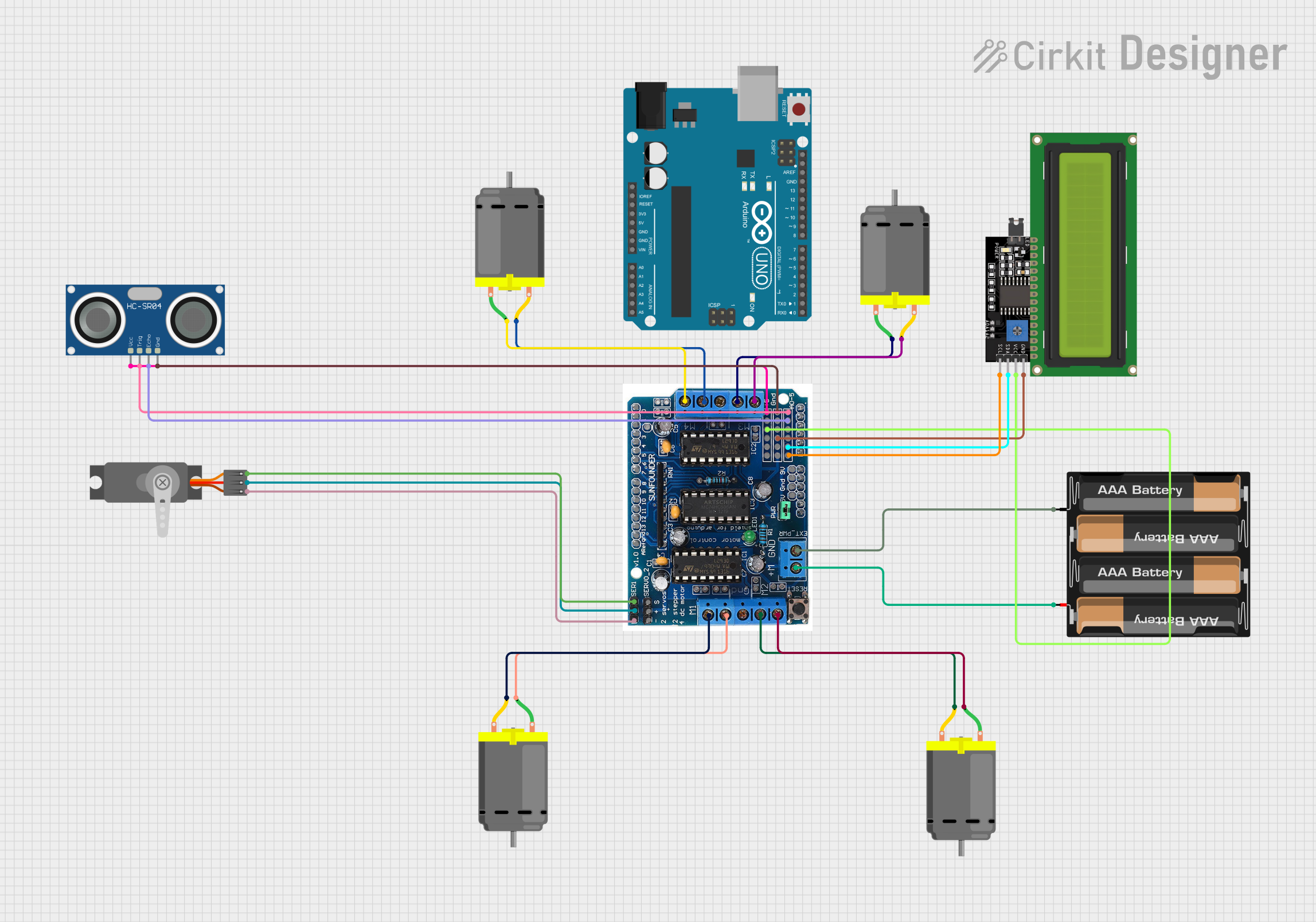
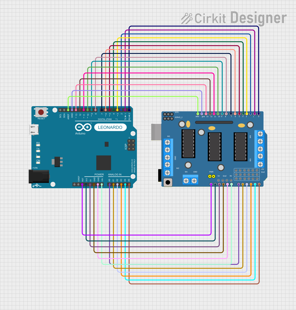
Explore Projects Built with L293D Driver Shield
Common Applications and Use Cases
- Robotics: Driving wheels or tracks
- Automation: Controlling conveyor belts or machinery
- Educational projects: Teaching motor control principles
- Hobbyist projects: RC cars, drones, or custom-built machines
Technical Specifications
Key Technical Details
- Motor Voltage (VM): 4.5V to 36V
- Logic Voltage (VSS): 5V (from Arduino board)
- Output Current: Up to 600mA per channel
- Peak Output Current: 1.2A per channel (non-repetitive)
- Thermal Shutdown: Yes
- Protection Diodes: Integrated
Pin Configuration and Descriptions
| Pin Number | Name | Description |
|---|---|---|
| 1 | M1A | Motor 1 output A |
| 2 | M1B | Motor 1 output B |
| 3 | M2A | Motor 2 output A |
| 4 | M2B | Motor 2 output B |
| 5 | +5V | Logic power supply (VSS) |
| 6 | VM | Motor power supply |
| 7 | GND | Ground |
| 8 | EN1 | Enable pin for Motor 1 |
| 9 | EN2 | Enable pin for Motor 2 |
Usage Instructions
How to Use the Component in a Circuit
Power Connections:
- Connect the motor power supply to the VM pin.
- Ensure the Arduino board is powered to provide logic power (VSS).
Motor Connections:
- Connect your DC motors to the M1 and M2 output pins.
- For a stepper motor, connect the coils to M1A/M1B and M2A/M2B.
Control Connections:
- Use digital output pins from the Arduino to control the EN1 and EN2 pins for enabling or disabling the motors.
Important Considerations and Best Practices
- Do not exceed the recommended voltage and current specifications.
- Use an external power supply for the motors if they require more current than the Arduino can provide.
- Ensure that the motors are correctly connected to avoid damage to the shield or motors.
- Always disconnect the power before making or changing connections.
Example Code for Arduino UNO
// Example code to control a DC motor with the L293D Driver Shield

#include <Arduino.h>

// Define motor control pins
const int motorPin1 = 3; // M1A
const int motorPin2 = 4; // M1B
const int enablePin = 9; // EN1

void setup() {
  // Set motor control pins as outputs
  pinMode(motorPin1, OUTPUT);
  pinMode(motorPin2, OUTPUT);
  pinMode(enablePin, OUTPUT);

  // Enable the motor
  digitalWrite(enablePin, HIGH);
}

void loop() {
  // Spin the motor in one direction
  digitalWrite(motorPin1, HIGH);
  digitalWrite(motorPin2, LOW);
  delay(2000);

  // Stop the motor
  digitalWrite(motorPin1, LOW);
  digitalWrite(motorPin2, LOW);
  delay(1000);

  // Spin the motor in the opposite direction
  digitalWrite(motorPin1, LOW);
  digitalWrite(motorPin2, HIGH);
  delay(2000);

  // Stop the motor
  digitalWrite(motorPin1, LOW);
  digitalWrite(motorPin2, LOW);
  delay(1000);
}
Troubleshooting and FAQs
Common Issues Users Might Face
- Motor not running: Check power supply connections, ensure the enable pin is set to HIGH.
- Motor running weakly: Verify that the power supply can deliver sufficient current.
- Overheating: Ensure the current draw is within the shield's limits; add heat sinks if necessary.
Solutions and Tips for Troubleshooting
- Double-check wiring and connections.
- Use a multimeter to verify power supply voltage and motor resistance.
- Test the L293D Driver Shield with a simple code to isolate the issue.
FAQs
Q: Can I control the speed of the motors using this shield? A: Yes, you can control the speed by using PWM signals on the enable pins.
Q: Is it possible to drive more than two motors with this shield? A: The L293D Driver Shield is designed to drive up to two DC motors or one stepper motor. To control more motors, additional shields or driver circuits are required.
Q: Can I stack another shield on top of the L293D Driver Shield? A: Yes, as long as the other shield is compatible and does not use the same pins required by the L293D Driver Shield.