How to Use l293d motor driver: Examples, Pinouts, and Specs
Introduction
The L293D is a popular motor driver IC capable of driving two DC motors simultaneously, with the ability to control both the direction and speed of the motors. It is widely used in robotics, small vehicle control, and various DIY projects where motor control is required.
Explore Projects Built with l293d motor driver

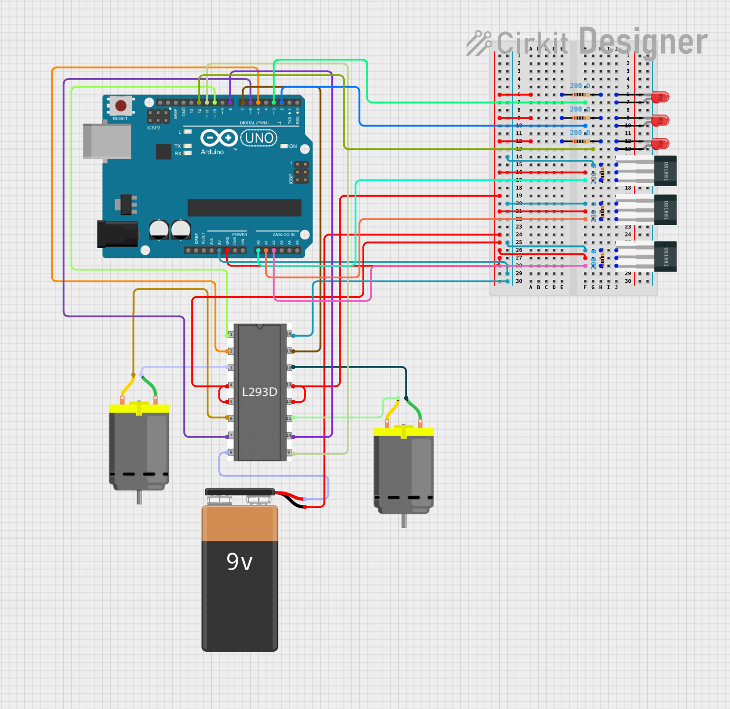
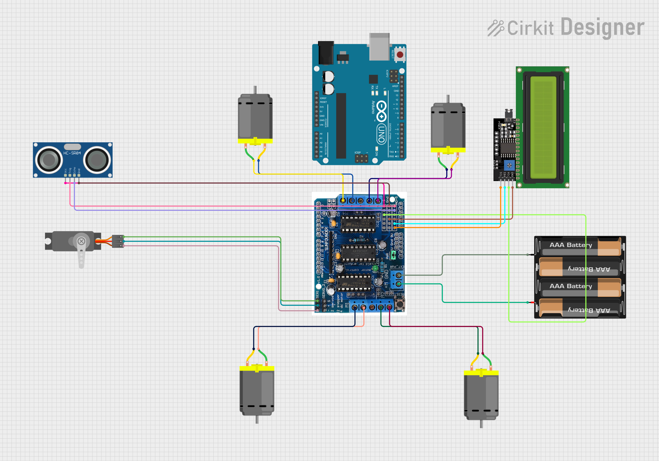
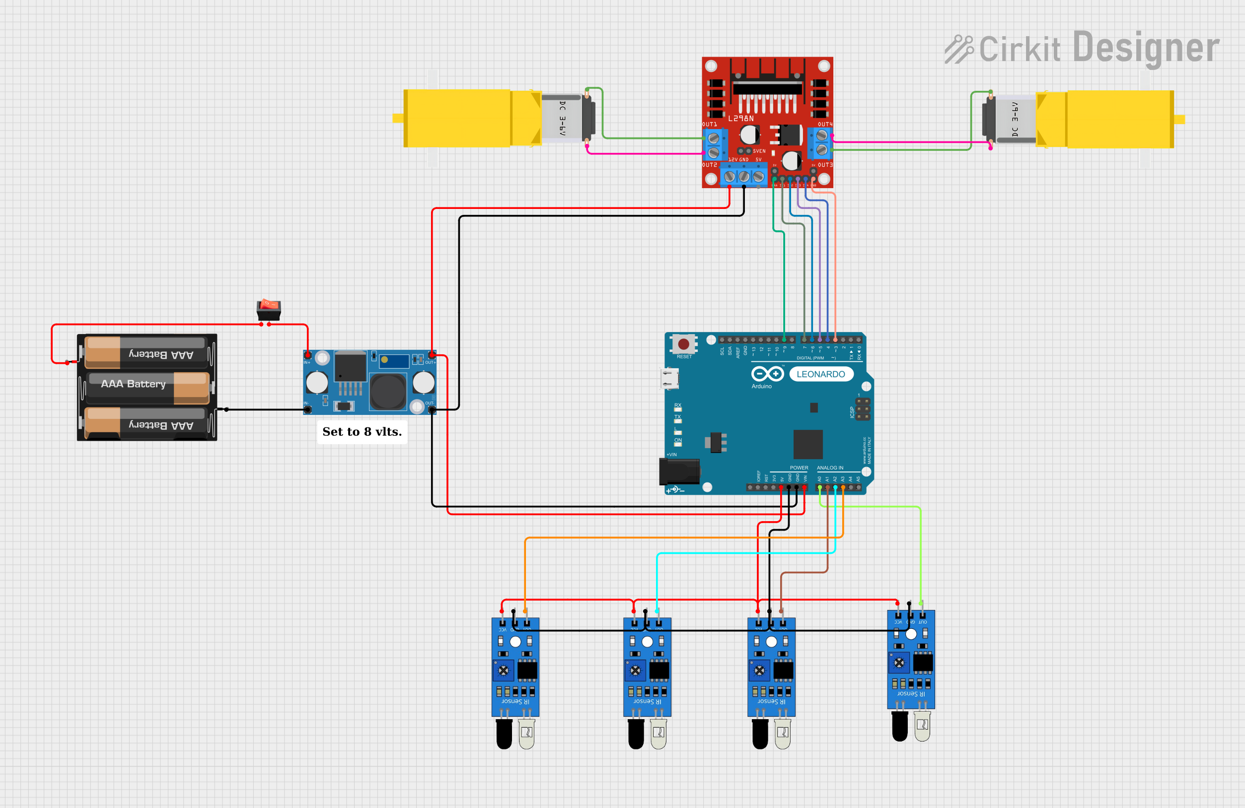
Explore Projects Built with l293d motor driver
Common Applications and Use Cases
- Robotics
- Automated Guided Vehicles (AGVs)
- Hobbyist projects
- Educational platforms for learning motor control
Technical Specifications
Key Technical Details
- Supply Voltage (Vcc1): 4.5V to 36V
- Logic Supply Voltage (Vcc2): 4.5V to 7V
- Output Current (each channel): 600mA
- Peak Output Current (each channel): 1.2A
- Enable Input Voltage: 4.5V to 7V
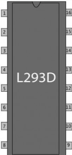
Pin Configuration and Descriptions
| Pin Number | Name | Description |
|---|---|---|
| 1 | Enable 1,2 | Enables motor driver channels 1 and 2 |
| 2 | Input 1 | Logic input for motor 1 direction |
| 3 | Output 1 | Output to motor 1 |
| 4, 5 | GND | Ground pins |
| 6 | Output 2 | Output to motor 1 |
| 7 | Input 2 | Logic input for motor 1 direction |
| 8 | Vcc2 | Motor supply voltage |
| 9 | Enable 3,4 | Enables motor driver channels 3 and 4 |
| 10 | Input 3 | Logic input for motor 2 direction |
| 11 | Output 3 | Output to motor 2 |
| 12, 13 | GND | Ground pins |
| 14 | Output 4 | Output to motor 2 |
| 15 | Input 4 | Logic input for motor 2 direction |
| 16 | Vcc1 | Logic supply voltage |
Usage Instructions
How to Use the L293D in a Circuit
- Connect Vcc1 (Pin 16) to a 5V supply for the logic part of the IC.
- Connect Vcc2 (Pin 8) to the motor power supply, which can range from 4.5V to 36V.
- Connect the ground pins (Pins 4, 5, 12, 13) to the common ground of the power supply and the control circuit.
- Connect the Enable pins (Pins 1 and 9) to logic high (5V) to enable the motor driver channels.
- Connect Input pins (Pins 2, 7, 10, 15) to the control signals that determine the direction of the motors.
- Connect Output pins (Pins 3, 6, 11, 14) to the motors.
- Use PWM signals on the Enable pins to control the speed of the motors.
Important Considerations and Best Practices
- Always use a decoupling capacitor close to the motor supply pin to filter out noise caused by motor operations.
- Do not exceed the maximum supply voltage and current ratings to prevent damage to the IC.
- Use heat sinks if operating near the peak current ratings for extended periods.
- Ensure that the motors do not draw more current than the IC can handle.
Example Code for Arduino UNO
// Define the motor control pins
#define MOTOR1_PIN1 2
#define MOTOR1_PIN2 3
#define MOTOR1_ENABLE 9

// Initialize the motor control pins
void setup() {
  pinMode(MOTOR1_PIN1, OUTPUT);
  pinMode(MOTOR1_PIN2, OUTPUT);
  pinMode(MOTOR1_ENABLE, OUTPUT);
}

// Function to control motor direction and speed
void controlMotor(int speed, bool direction) {
  digitalWrite(MOTOR1_PIN1, direction);
  digitalWrite(MOTOR1_PIN2, !direction);
  analogWrite(MOTOR1_ENABLE, speed);
}

// Main program loop
void loop() {
  // Set motor to run at 50% speed in one direction
  controlMotor(128, true);
  delay(2000);

  // Set motor to run at 50% speed in the opposite direction
  controlMotor(128, false);
  delay(2000);
}
Troubleshooting and FAQs
Common Issues Users Might Face
- Motor not running: Check power supply connections, ensure enable pins are high.
- Motor running only in one direction: Verify the logic inputs for correct direction control.
- Motor stalling or weak: Ensure the power supply can deliver sufficient current.
Solutions and Tips for Troubleshooting
- Double-check wiring and connections.
- Use a multimeter to verify the voltage at the motor driver inputs and outputs.
- Replace the L293D if it overheats or shows signs of damage.
FAQs
Q: Can I control stepper motors with the L293D? A: Yes, the L293D can be used to control bipolar stepper motors with the correct wiring and control signals.
Q: What is the function of the enable pins? A: The enable pins turn the motor driver channels on or off. When high, the channels are active, and when low, the channels are inactive.
Q: How can I control the speed of the motors? A: Speed control can be achieved by applying PWM signals to the enable pins of the L293D.
Q: Can I use the L293D without an Arduino? A: Yes, the L293D can be used with any microcontroller or even simple switch-based control circuits.