How to Use Quectel: Examples, Pinouts, and Specs
Introduction
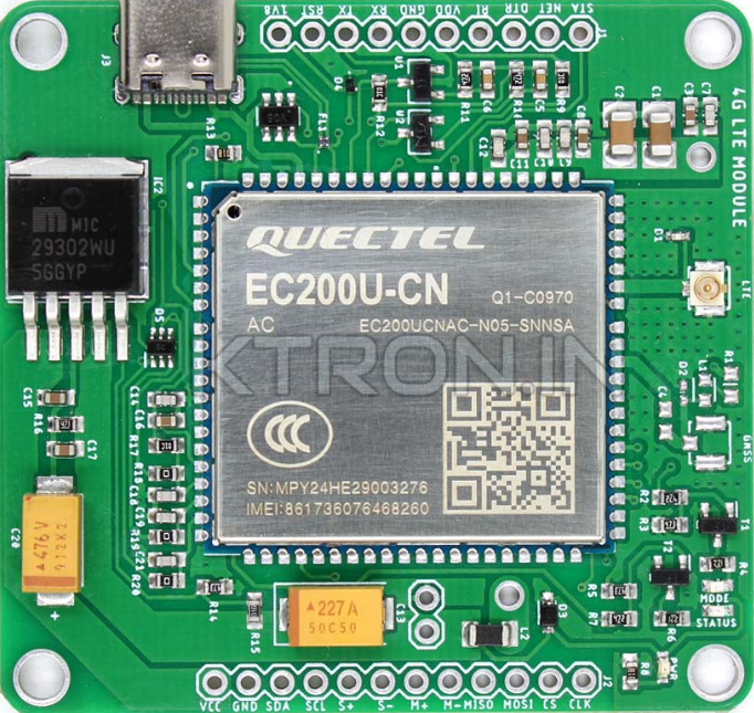
The Quectel EC200U-CN is a high-performance LTE Cat 4 module designed for IoT and M2M (Machine-to-Machine) applications. It supports a wide range of communication standards, including LTE and GNSS, making it ideal for applications requiring reliable and high-speed connectivity. The module is compact, power-efficient, and versatile, enabling seamless integration into various IoT devices.
Explore Projects Built with Quectel


Explore Projects Built with Quectel
Common Applications and Use Cases
- Smart meters and smart grids
- Industrial automation and control
- Asset tracking and fleet management
- Smart home and security systems
- Wearable devices
- Remote monitoring and telematics
Technical Specifications
The Quectel EC200U-CN module is designed to deliver robust performance in IoT applications. Below are its key technical specifications:
General Specifications
| Parameter | Description |
|---|---|
| Manufacturer | Quectel |
| Part Number | EC200U-CN |
| Communication Standard | LTE Cat 4 |
| GNSS Support | GPS, GLONASS, BeiDou, Galileo |
| Operating Voltage | 3.3V to 4.3V |
| Operating Temperature | -40°C to +85°C |
| Dimensions | 29.0mm × 32.0mm × 2.4mm |
Electrical Characteristics
| Parameter | Min Value | Typical Value | Max Value | Unit |
|---|---|---|---|---|
| Supply Voltage (VCC) | 3.3 | 3.8 | 4.3 | V |
| Power Consumption (Idle) | - | 15 | - | mA |
| Power Consumption (Max) | - | 2,000 | - | mA |
Pin Configuration and Descriptions
The EC200U-CN module has multiple pins for power, communication, and control. Below is the pin configuration:
| Pin Number | Pin Name | Description |
|---|---|---|
| 1 | VCC | Power supply input (3.3V to 4.3V) |
| 2 | GND | Ground |
| 3 | TXD | UART Transmit Data |
| 4 | RXD | UART Receive Data |
| 5 | RESET | Reset input (active low) |
| 6 | GNSS_TXD | GNSS UART Transmit Data |
| 7 | GNSS_RXD | GNSS UART Receive Data |
| 8 | USB_DP | USB Data Positive |
| 9 | USB_DM | USB Data Negative |
| 10 | ANT | Antenna interface |
Usage Instructions
The Quectel EC200U-CN module can be integrated into IoT devices for LTE and GNSS connectivity. Below are the steps and best practices for using the module:
Basic Circuit Connection
- Power Supply: Connect the VCC pin to a stable 3.8V power source and the GND pin to ground.
- UART Communication: Connect the TXD and RXD pins to the corresponding UART pins of your microcontroller or development board (e.g., Arduino UNO).
- Antenna: Attach an appropriate LTE/GNSS antenna to the ANT pin for optimal signal reception.
- Reset: Use the RESET pin to reset the module when necessary (active low).
Important Considerations
- Ensure the power supply is stable and within the specified voltage range to avoid damage to the module.
- Use proper ESD protection when handling the module to prevent static discharge damage.
- Place the antenna in a location with minimal interference for better signal quality.
- If using GNSS functionality, ensure the antenna has a clear view of the sky for accurate positioning.
Example: Connecting to an Arduino UNO
Below is an example of how to interface the EC200U-CN module with an Arduino UNO for basic UART communication:
Circuit Diagram
- Connect the EC200U-CN TXD pin to Arduino UNO RX (Pin 0).
- Connect the EC200U-CN RXD pin to Arduino UNO TX (Pin 1).
- Connect the VCC and GND pins to a 3.8V power source and ground, respectively.
Arduino Code Example
#include <SoftwareSerial.h>

// Define RX and TX pins for SoftwareSerial
SoftwareSerial EC200U(10, 11); // RX = Pin 10, TX = Pin 11

void setup() {
  // Initialize serial communication with the module
  EC200U.begin(9600); // Set baud rate to 9600
  Serial.begin(9600); // For debugging via Serial Monitor

  // Send initialization command to the module
  EC200U.println("AT"); // Send AT command to check communication
}

void loop() {
  // Check if the module sends any data
  if (EC200U.available()) {
    String response = EC200U.readString(); // Read response from the module
    Serial.println(response); // Print response to Serial Monitor
  }

  // Check if user sends data via Serial Monitor
  if (Serial.available()) {
    String command = Serial.readString(); // Read user input
    EC200U.println(command); // Send command to the module
  }
}
Notes:
- Replace
10and11inSoftwareSerialwith the actual pins you are using for RX and TX. - Ensure the baud rate matches the default baud rate of the EC200U-CN module.
Troubleshooting and FAQs
Common Issues and Solutions
Module Not Responding to AT Commands
- Cause: Incorrect baud rate or wiring.
- Solution: Verify the baud rate and ensure proper connections between the module and microcontroller.
No GNSS Signal
- Cause: Antenna placement or interference.
- Solution: Place the antenna in an open area with a clear view of the sky.
High Power Consumption
- Cause: Module operating in high-power mode.
- Solution: Use power-saving modes if supported by your application.
Unstable Communication
- Cause: Noise or unstable power supply.
- Solution: Use decoupling capacitors near the power pins and ensure a clean power source.
FAQs
Can the EC200U-CN module be powered directly from a 5V source?
- No, the module requires a supply voltage between 3.3V and 4.3V. Use a voltage regulator if necessary.
What is the maximum data rate supported by the module?
- The EC200U-CN supports LTE Cat 4 with a maximum download speed of 150 Mbps and upload speed of 50 Mbps.
Does the module support SMS functionality?
- Yes, the EC200U-CN supports SMS sending and receiving via AT commands.
Can I use the module with a Raspberry Pi?
- Yes, the module can be connected to a Raspberry Pi via UART or USB interface.
By following this documentation, users can effectively integrate the Quectel EC200U-CN module into their IoT projects and troubleshoot common issues.