How to Use Garmin LIDAR-Lite Optical Distance LED Sensor - V4: Examples, Pinouts, and Specs
Introduction
The Garmin LIDAR-Lite Optical Distance LED Sensor - V4 is a compact and lightweight optical distance sensor that utilizes LIDAR (Light Detection and Ranging) technology to measure distances with high accuracy. This sensor is designed for high-speed measurement and is ideal for applications requiring precise distance measurements, such as robotics, drones, industrial automation, and IoT systems. Its small form factor and low power consumption make it a versatile choice for a wide range of projects.
Explore Projects Built with Garmin LIDAR-Lite Optical Distance LED Sensor - V4
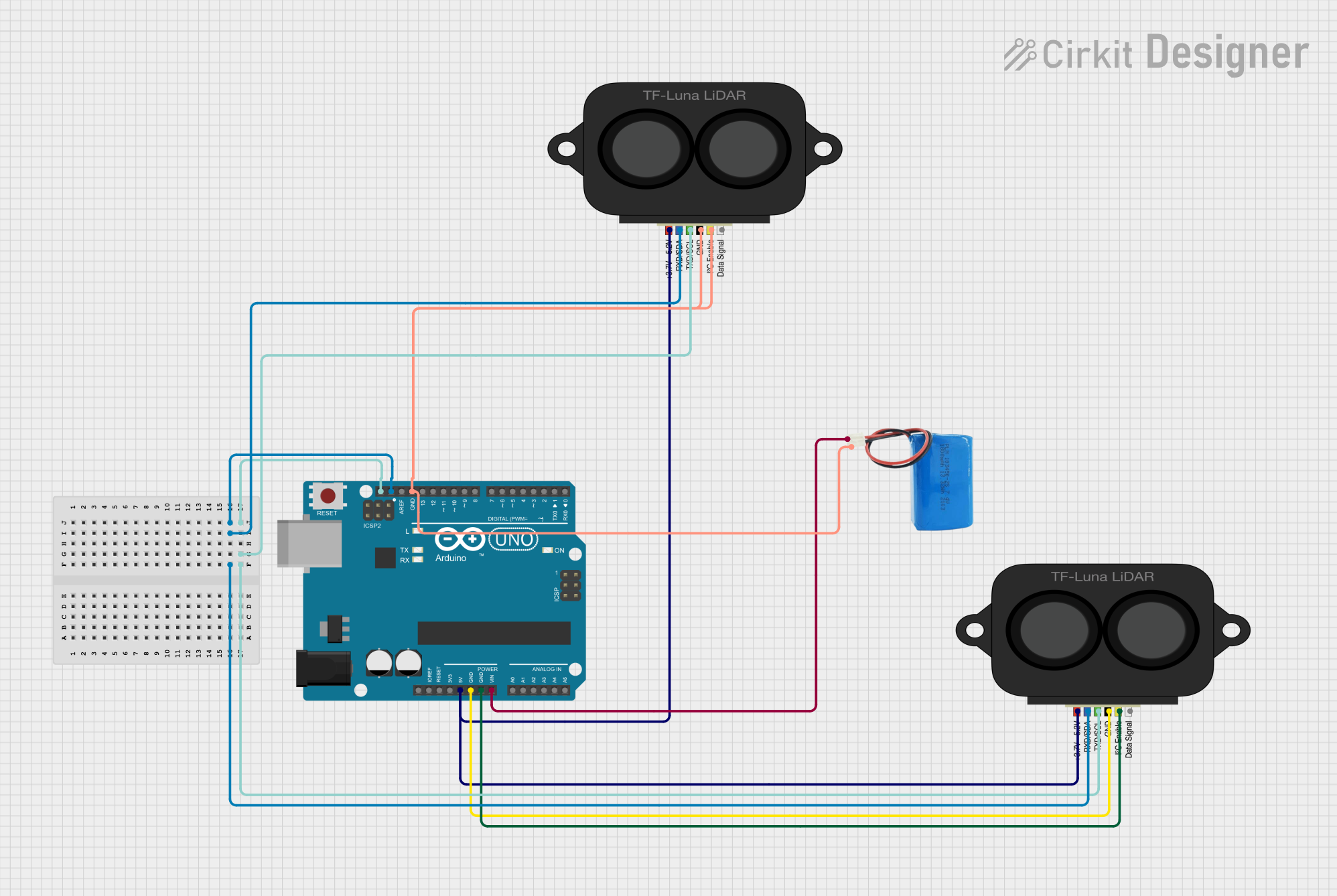

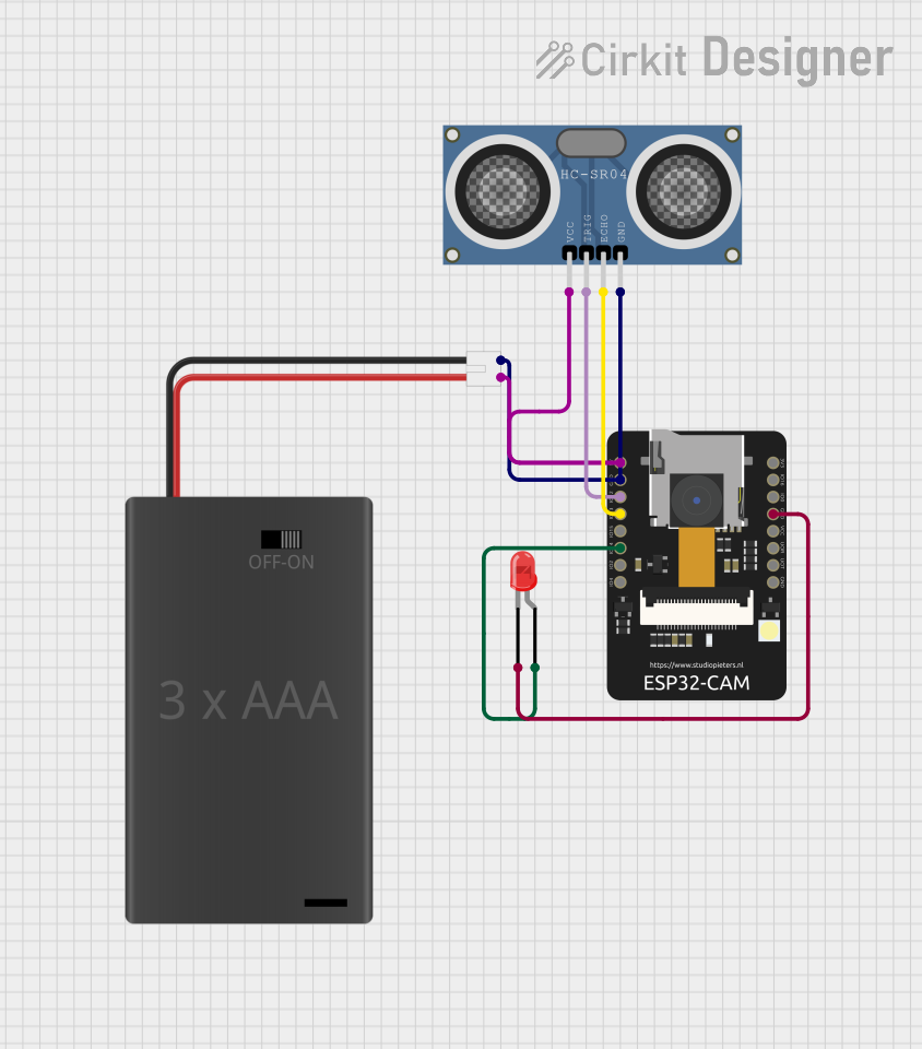
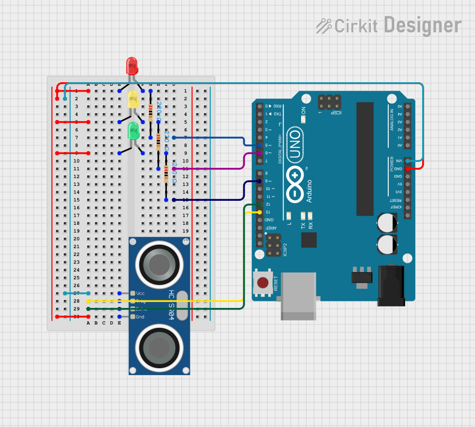
Explore Projects Built with Garmin LIDAR-Lite Optical Distance LED Sensor - V4
Technical Specifications
- Measurement Range: 5 cm to 10 m (reflective target)
- Accuracy: ±2.5 cm
- Measurement Frequency: Up to 500 Hz
- Interface: I2C or PWM
- Input Voltage: 4.75 V to 5.5 V
- Current Consumption: 85 mA (typical during operation)
- Operating Temperature: -20°C to 60°C
- Dimensions: 48 mm x 40 mm x 20 mm
- Weight: 22 g
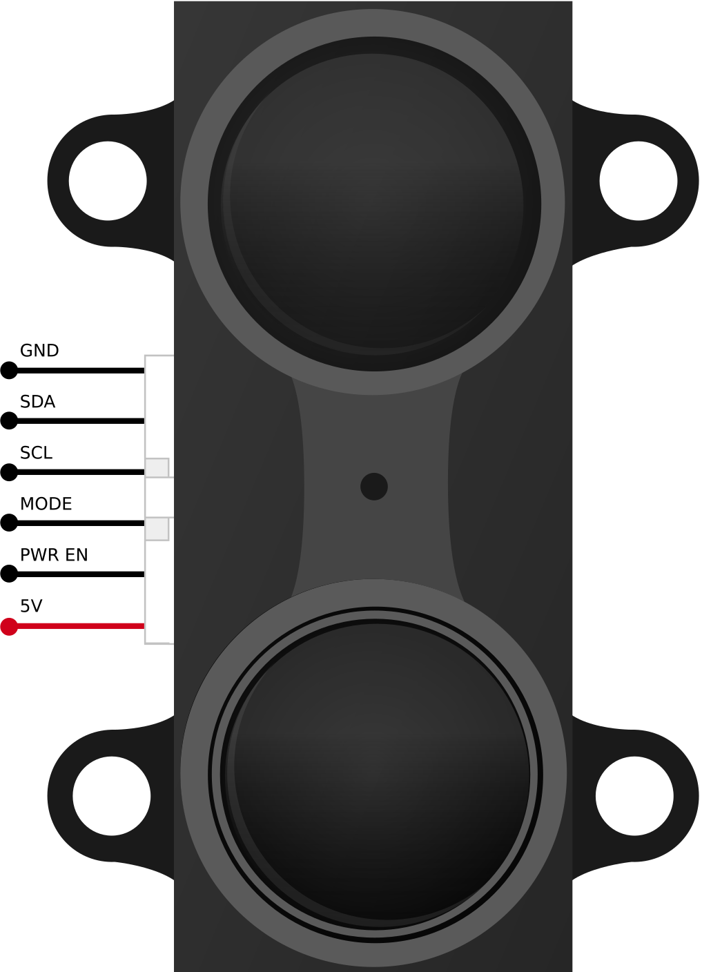
Pin Configuration and Descriptions
The Garmin LIDAR-Lite V4 sensor has a 6-pin connector. Below is the pinout and description:
| Pin | Name | Description |
|---|---|---|
| 1 | Power (VCC) | Connect to a 5V power supply. |
| 2 | Ground (GND) | Connect to the ground of the power supply. |
| 3 | Mode Control | Used to select the communication mode (I2C or PWM). |
| 4 | I2C SCL | Serial Clock Line for I2C communication. |
| 5 | I2C SDA | Serial Data Line for I2C communication. |
| 6 | PWM Output | Outputs a PWM signal proportional to the measured distance (if PWM mode is used). |
Usage Instructions
Connecting the Sensor
- Power Supply: Connect the VCC pin to a 5V power source and the GND pin to ground.
- Communication Mode:
- For I2C communication, connect the SCL and SDA pins to the corresponding pins on your microcontroller (e.g., Arduino).
- For PWM mode, connect the PWM Output pin to a digital input pin on your microcontroller.
- Use the Mode Control pin to configure the desired communication mode (refer to the sensor's datasheet for details).
- Pull-Up Resistors: If using I2C, ensure that pull-up resistors (typically 4.7 kΩ) are connected to the SCL and SDA lines.
Example: Using with Arduino UNO (I2C Mode)
Below is an example code snippet to interface the Garmin LIDAR-Lite V4 sensor with an Arduino UNO using I2C communication:
#include <Wire.h> // Include the Wire library for I2C communication

#define LIDAR_ADDRESS 0x62 // Default I2C address of the LIDAR-Lite V4
#define MEASURE_REGISTER 0x00 // Register to initiate measurement
#define DISTANCE_REGISTER 0x10 // Register to read distance data

void setup() {
  Wire.begin(); // Initialize I2C communication
  Serial.begin(9600); // Initialize serial communication for debugging
  Serial.println("LIDAR-Lite V4 Initialization...");
}

void loop() {
  // Start a measurement by writing to the measure register
  Wire.beginTransmission(LIDAR_ADDRESS);
  Wire.write(MEASURE_REGISTER);
  Wire.write(0x04); // Command to start measurement
  Wire.endTransmission();

  delay(20); // Wait for the measurement to complete

  // Read the distance data from the distance register
  Wire.beginTransmission(LIDAR_ADDRESS);
  Wire.write(DISTANCE_REGISTER);
  Wire.endTransmission();

  Wire.requestFrom(LIDAR_ADDRESS, 2); // Request 2 bytes of distance data
  if (Wire.available() == 2) {
    uint16_t distance = Wire.read() << 8 | Wire.read(); // Combine MSB and LSB
    Serial.print("Distance: ");
    Serial.print(distance);
    Serial.println(" cm");
  }

  delay(100); // Delay before the next measurement
}
Best Practices
- Ensure the sensor is mounted securely to avoid vibrations that could affect measurements.
- Avoid direct exposure to sunlight or reflective surfaces near the sensor, as these may interfere with readings.
- Use proper decoupling capacitors near the power supply pins to reduce noise.
- If using I2C, ensure the bus length is minimized to maintain signal integrity.
Troubleshooting and FAQs
Common Issues
No Data Received via I2C:
- Ensure the I2C address (default: 0x62) matches the one in your code.
- Check the pull-up resistors on the SCL and SDA lines.
- Verify the wiring and connections.
Inaccurate Distance Measurements:
- Ensure there are no reflective or transparent objects in the sensor's field of view.
- Check for proper alignment of the sensor with the target.
Sensor Not Powering On:
- Verify the input voltage is within the specified range (4.75 V to 5.5 V).
- Check the power supply connections and ensure sufficient current is available.
FAQs
Q: Can the sensor measure distances beyond 10 meters?
A: No, the maximum measurement range is 10 meters for reflective targets. For non-reflective targets, the range may be shorter.
Q: Can I use the sensor with a 3.3V microcontroller?
A: Yes, but you will need a logic level shifter for the I2C or PWM signals, as the sensor operates at 5V logic levels.
Q: How can I increase measurement accuracy?
A: Use a stable power supply, avoid environmental interference (e.g., sunlight), and ensure the sensor is properly aligned with the target.
Q: Is the sensor waterproof?
A: No, the Garmin LIDAR-Lite V4 is not waterproof. Use appropriate enclosures for outdoor applications.