How to Use Inductive Sensor: Examples, Pinouts, and Specs
Introduction
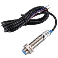
An inductive sensor is a non-contact electronic proximity sensor that is used to detect the presence of metallic objects. Utilizing the principles of electromagnetic induction, the sensor generates an oscillating electromagnetic field, which is disturbed by the approach of a metal object. This disturbance is detected and converted into an electrical output signal. Inductive sensors are widely used in industrial automation, robotics, and automotive applications due to their durability, reliability, and long service life.
Explore Projects Built with Inductive Sensor
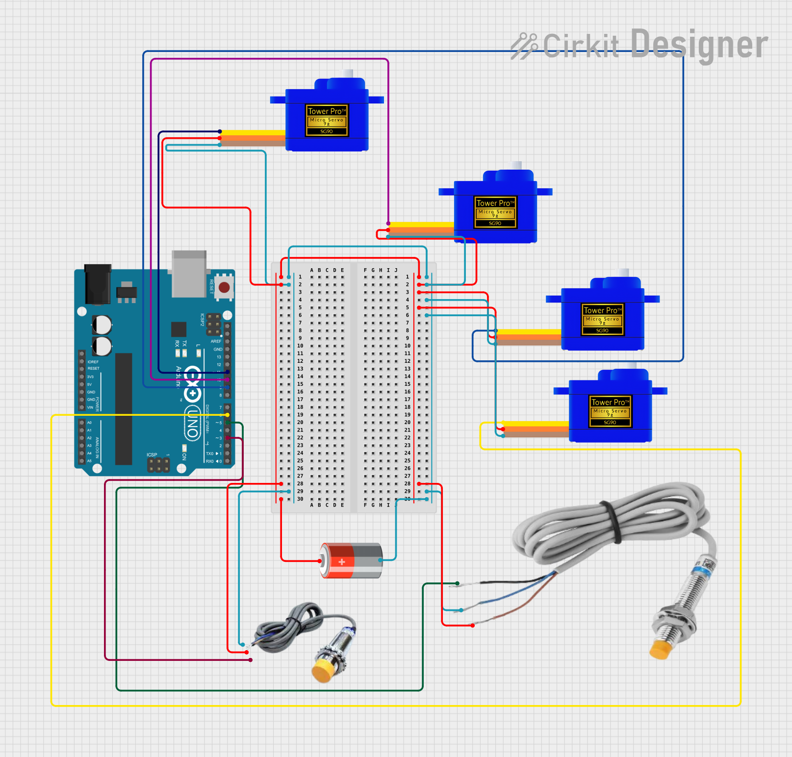

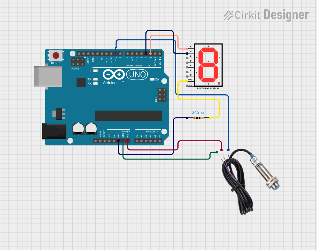
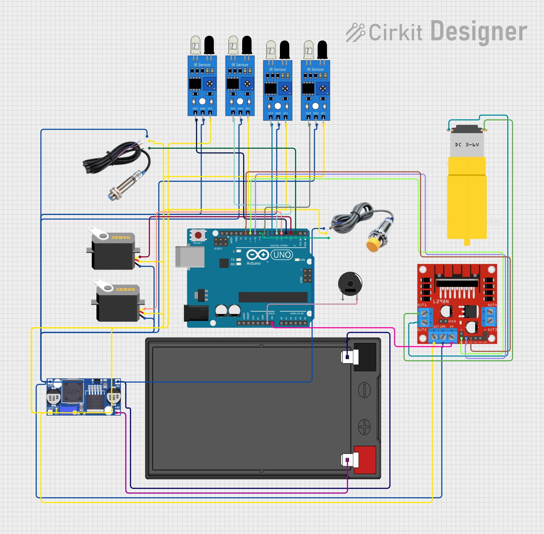
Explore Projects Built with Inductive Sensor
Common Applications and Use Cases
- Position sensing in machine tools and industrial automation
- Speed detection of metallic parts in conveyor systems
- Counting metallic objects in production lines
- End-of-travel detection in mechanical systems
- Detection of metallic components in safety and security systems
Technical Specifications
Key Technical Details
- Supply Voltage (Vcc): Typically 10-30V DC
- Output Current: Usually up to 200 mA
- Sensing Distance: Ranges from a few millimeters to several centimeters
- Frequency: Can vary, often in the range of hundreds of Hz to a few kHz
- Operating Temperature: -25°C to +70°C (varies by model)
Pin Configuration and Descriptions
| Pin Number | Description | Notes |
|---|---|---|
| 1 | Vcc (Power Supply) | Connect to positive voltage supply |
| 2 | Output | Switching signal (NPN/PNP) |
| 3 | Ground | Connect to system ground |
Usage Instructions
How to Use the Component in a Circuit
- Power Supply Connection: Connect the Vcc pin to a DC power supply within the sensor's specified voltage range.
- Ground Connection: Connect the ground pin to the common ground in your circuit.
- Output Connection: Connect the output pin to the input of a microcontroller, relay, or LED indicator for signal processing or visualization.
Important Considerations and Best Practices
- Ensure that the sensor is properly aligned with the target metallic object for optimal detection.
- Avoid placing the sensor near strong electromagnetic fields to prevent interference.
- Use shielded cables for connections, especially in environments with high electrical noise.
- Test the sensor with the specific metals used in the application, as different metals can affect the sensing distance.
Troubleshooting and FAQs
Common Issues Users Might Face
- Sensor not detecting metal: Check the alignment, sensing distance, and if the metal type is compatible with the sensor's specifications.
- False triggering: Ensure there are no unintended metallic objects within the sensing range and check for electromagnetic interference.
Solutions and Tips for Troubleshooting
- Verify the power supply voltage and connections.
- Inspect the sensor for any physical damage or contamination.
- Test the sensor output with a multimeter to confirm proper operation.
- If the sensor is used in a noisy environment, consider using a sensor with a higher immunity to interference.
FAQs
Q: Can inductive sensors detect non-metallic objects? A: No, inductive sensors are designed to detect metallic objects only.
Q: What is the difference between NPN and PNP output? A: NPN sensors sink current (output goes low when metal is detected), while PNP sensors source current (output goes high when metal is detected).
Q: How do I choose the correct sensing distance? A: The sensing distance should be chosen based on the size of the metallic object and the gap you expect between the sensor and the object in your application.
Example Code for Arduino UNO
// Define the sensor output pin connected to the Arduino
const int inductiveSensorPin = 2;

void setup() {
  // Set the inductive sensor pin as an input
  pinMode(inductiveSensorPin, INPUT);
  // Initialize serial communication at 9600 bits per second
  Serial.begin(9600);
}

void loop() {
  // Read the state of the inductive sensor output
  int sensorState = digitalRead(inductiveSensorPin);

  // Print the sensor state to the Serial Monitor
  Serial.println(sensorState);

  // Add a delay for stability
  delay(100);
}
Note: The above code assumes an NPN-type inductive sensor with the output connected to digital pin 2 of the Arduino UNO. The sensor's Vcc and ground should be connected to the Arduino's 5V and GND, respectively. Adjust the pin number and power connections as necessary for your specific setup.