How to Use Membrane Matrix Keypad: Examples, Pinouts, and Specs
Introduction
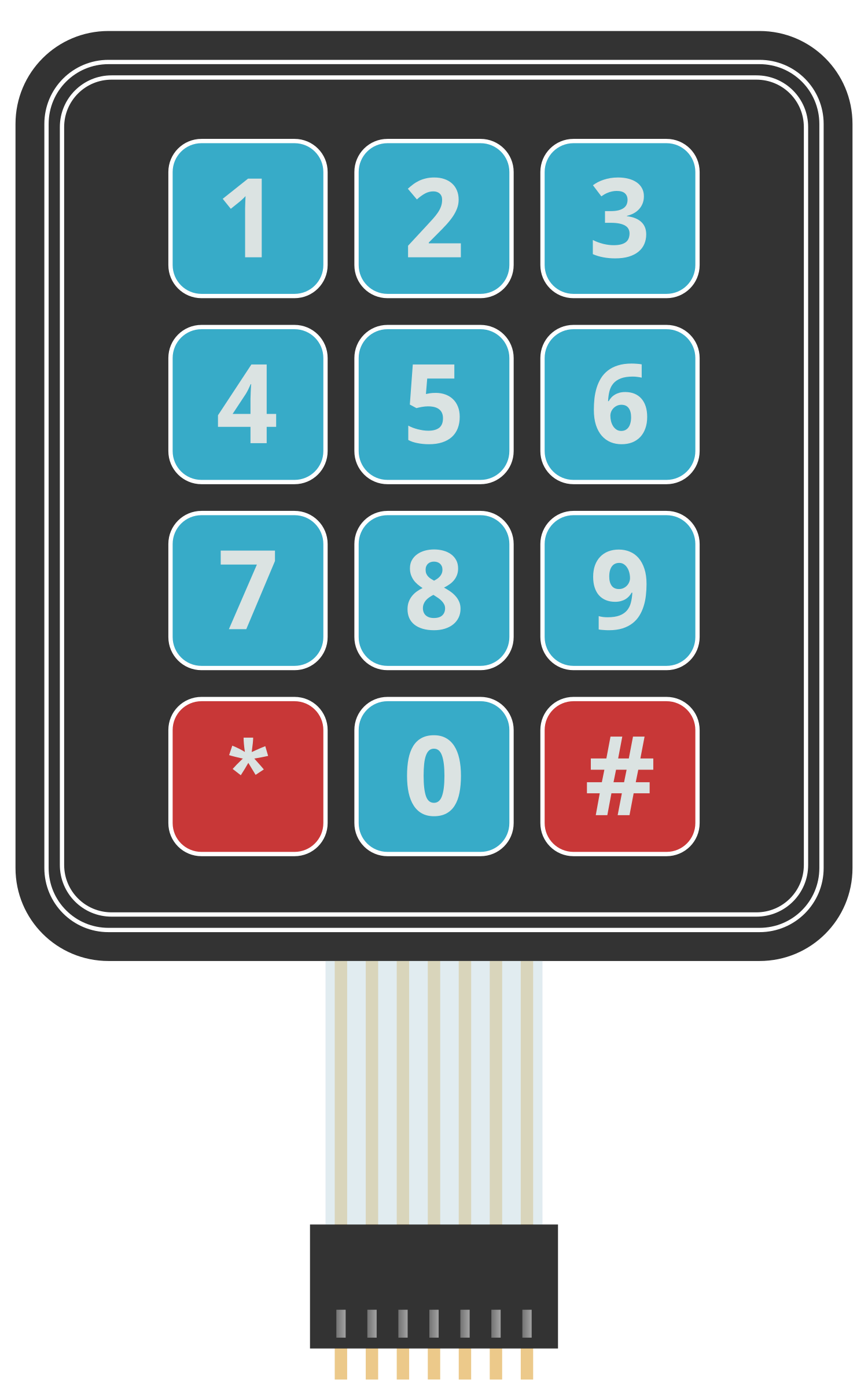
The Membrane Matrix Keypad is a user interface component that allows users to input data into an electronic device. It consists of a flexible membrane with a grid of buttons, each representing a different key. When a button is pressed, it makes contact with a conductive pad on the underlying layer, closing the circuit and sending a signal to the device's processor. These keypads are commonly used in applications such as security systems, telephone systems, and various control panels due to their durability, low profile, and ease of cleaning.
Explore Projects Built with Membrane Matrix Keypad
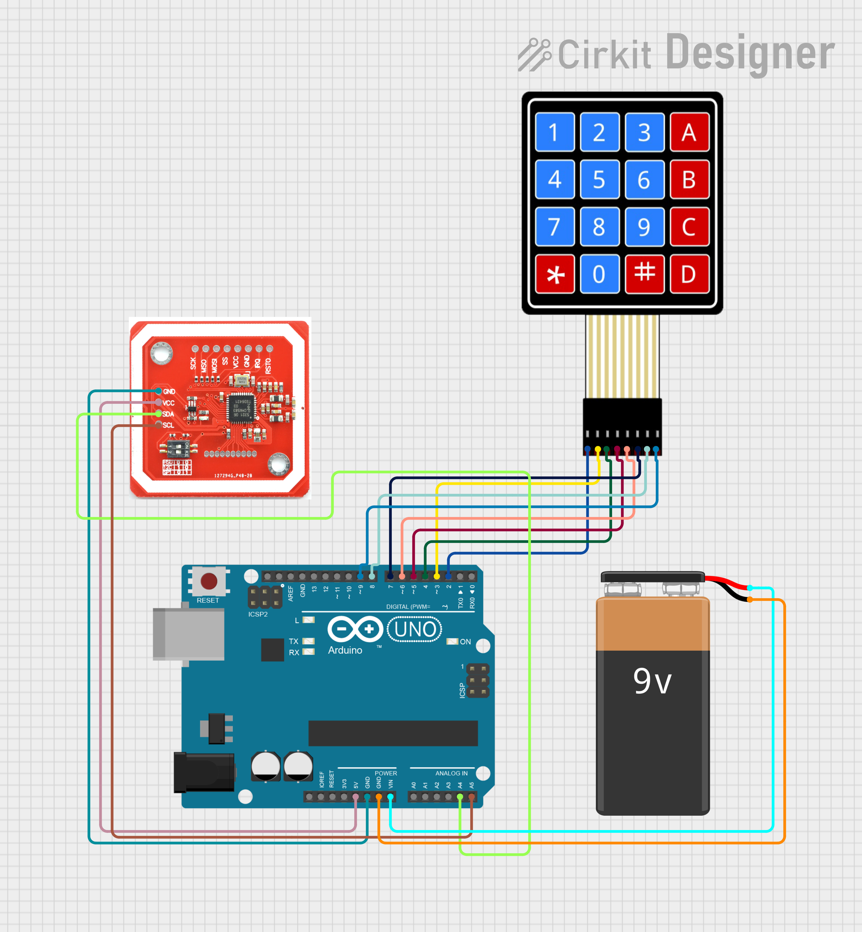
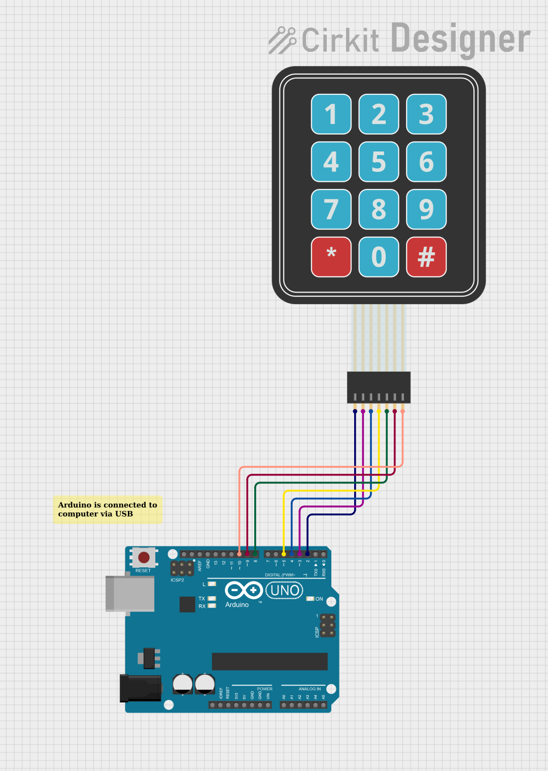

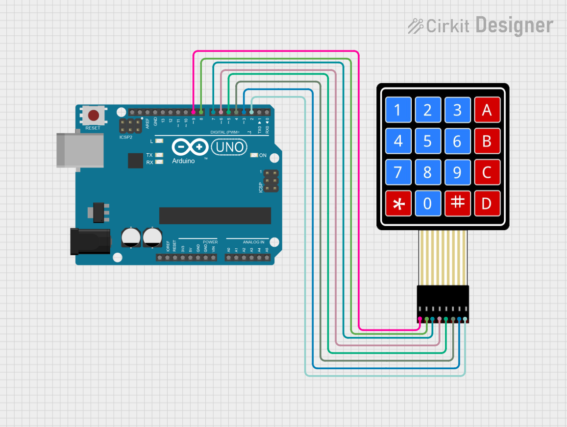
Explore Projects Built with Membrane Matrix Keypad
Technical Specifications
Key Technical Details
- Operating Voltage: Typically 3.3V to 5V
- Current Consumption: Depends on usage, generally very low
- Contact Bounce: Typically less than 5ms
- Operating Force: 20 to 500g
- Life Expectancy: 1 million to 5 million cycles per key
Pin Configuration and Descriptions
| Pin Number | Description |
|---|---|
| 1 | Row 1 |
| 2 | Row 2 |
| 3 | Row 3 |
| 4 | Row 4 (if applicable) |
| 5 | Column 1 |
| 6 | Column 2 |
| 7 | Column 3 |
| 8 | Column 4 (if applicable) |
Note: The pin configuration may vary depending on the number of keys on the keypad. The above table is for a common 4x4 matrix keypad.
Usage Instructions
How to Use the Component in a Circuit
Connect the Rows and Columns to Microcontroller Pins:
- Assign digital I/O pins on your microcontroller to each row and column of the keypad.
- Ensure that the microcontroller is set to provide a pull-up resistor on the row pins.
Scan the Keypad:
- Set all row pins to input mode.
- Set all column pins to output and drive them low.
- Scan the rows by setting one row high at a time and checking which column reads high.
Debounce the Keys:
- Implement a debounce algorithm in your code to ensure that each keypress is registered only once.
Key Detection:
- When a key is pressed, the corresponding row and column will be connected, allowing you to determine which key was pressed based on the row and column that are active.
Important Considerations and Best Practices
- Debouncing: Implement software debouncing to handle contact bounce which can cause multiple detections for a single press.
- Ghosting: In a matrix without diodes, pressing multiple keys simultaneously can cause 'ghost' presses. Avoid pressing multiple keys at the same time or use a keypad with diodes.
- Power Consumption: To save power, especially in battery-operated devices, scan the keypad only when necessary or use interrupt-driven scanning.
- Mounting: Ensure the keypad is securely mounted to prevent flexing, which can lead to unreliable keypress detection.
Troubleshooting and FAQs
Common Issues
- Keys not registering: Check connections and ensure that the microcontroller pins are correctly configured.
- Multiple keypresses detected for a single press: Implement or adjust your debounce algorithm.
- Inconsistent keypress detection: Ensure that the keypad is mounted on a stable surface.
Solutions and Tips for Troubleshooting
- Check Wiring: Verify that all connections are secure and that there are no shorts or open circuits.
- Test Each Key Individually: Isolate the issue by testing each key one at a time.
- Software Debugging: Use serial output to debug the keypress detection process in your code.
Example Code for Arduino UNO
#include <Keypad.h>

const byte ROWS = 4; // Four rows
const byte COLS = 4; // Four columns

// Define the Keymap
char keys[ROWS][COLS] = {
  {'1','2','3','A'},
  {'4','5','6','B'},
  {'7','8','9','C'},
  {'*','0','#','D'}
};

// Connect keypad ROW0, ROW1, ROW2 and ROW3 to these Arduino pins.
byte rowPins[ROWS] = {9, 8, 7, 6};

// Connect keypad COL0, COL1 and COL2 to these Arduino pins.
byte colPins[COLS] = {5, 4, 3, 2};

// Create the Keypad
Keypad keypad = Keypad(makeKeymap(keys), rowPins, colPins, ROWS, COLS);

void setup() {
  Serial.begin(9600);
}

void loop() {
  char key = keypad.getKey();

  if (key) {
    Serial.println(key);
  }
}
Note: The above code uses the Keypad library which can be installed via the Arduino Library Manager.
Code Comments
#include <Keypad.h>: Includes the Keypad library.const byte ROWSandconst byte COLS: Define the number of rows and columns.char keys[ROWS][COLS]: Defines the keymap of the keypad.byte rowPins[ROWS]andbyte colPins[COLS]: Arrays to hold the pin numbers connected to the rows and columns.Keypad keypad: Creates a Keypad object.Serial.begin(9600): Initializes serial communication.char key = keypad.getKey(): Checks for a keypress and stores it inkey.if (key) { Serial.println(key); }: If a key is pressed, print it to the serial monitor.
This documentation provides a comprehensive guide to integrating a Membrane Matrix Keypad into your electronic projects. For further assistance, consult the datasheet of your specific keypad model or reach out to the community forums for support.