How to Use Adafruit bd25185 60106: Examples, Pinouts, and Specs
Introduction
The Adafruit BQ25185 6106 is a highly efficient, compact, and versatile power management IC designed for battery charging and regulation. Manufactured by Adafruit, this component is ideal for applications requiring precise battery management, such as wearable devices, IoT gadgets, and portable electronics. It supports single-cell Li-Ion and Li-Polymer batteries and integrates multiple features, including a linear charger, a regulated output, and battery protection.
Explore Projects Built with Adafruit bd25185 60106


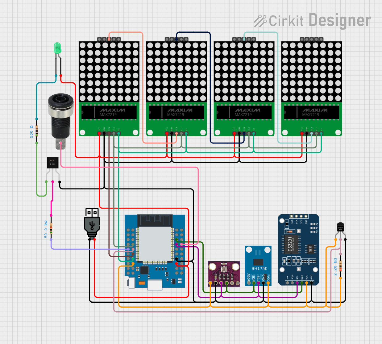
Explore Projects Built with Adafruit bd25185 60106
Common Applications and Use Cases
- Wearable electronics
- Internet of Things (IoT) devices
- Portable medical devices
- Low-power consumer electronics
- Battery-powered sensors
Technical Specifications
The Adafruit BQ25185 6106 offers a range of features tailored for efficient battery management. Below are the key technical details:
Key Technical Details
| Parameter | Value |
|---|---|
| Input Voltage Range | 3.6V to 6.6V |
| Battery Charge Voltage | Configurable up to 4.2V |
| Charge Current | Programmable up to 500mA |
| Quiescent Current | 700nA (typical) |
| Output Voltage (LDO Mode) | 1.8V to 3.3V (configurable) |
| Battery Protection | Overvoltage, undervoltage, and short-circuit |
| Package Type | 12-pin DFN |
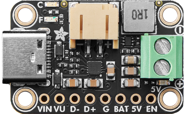
Pin Configuration and Descriptions
The BQ25185 6106 features a 12-pin DFN package. Below is the pinout description:
| Pin Number | Pin Name | Description |
|---|---|---|
| 1 | PMID | Input/output for the power path |
| 2 | SYS | System output voltage |
| 3 | BAT | Battery connection |
| 4 | TS | Temperature sense input |
| 5 | ISET | Charge current programming |
| 6 | GND | Ground |
| 7 | ILIM | Input current limit programming |
| 8 | VIN | Input power supply |
| 9 | CE | Charge enable (active low) |
| 10 | STAT | Charge status indicator |
| 11 | EN_LDO | Enable pin for LDO output |
| 12 | LDO | Low-dropout regulator output |
Usage Instructions
The Adafruit BQ25185 6106 is straightforward to use in battery-powered circuits. Below are the steps and considerations for integrating it into your design.
How to Use the Component in a Circuit
- Power Input: Connect the VIN pin to a power source (3.6V to 6.6V). Ensure the input voltage is within the specified range.
- Battery Connection: Attach the positive terminal of the battery to the BAT pin and the negative terminal to GND.
- Charge Current Configuration: Use a resistor on the ISET pin to set the desired charge current. Refer to the datasheet for resistor values.
- System Output: Connect the SYS pin to the load that requires regulated power.
- LDO Output: If using the LDO, connect the EN_LDO pin to enable the output and configure the desired voltage.
- Temperature Monitoring: Attach a thermistor to the TS pin for battery temperature monitoring.
- Charge Enable: Use the CE pin to enable or disable charging. Pull it low to enable charging.
Important Considerations and Best Practices
- Thermal Management: Ensure proper heat dissipation, especially when operating at high charge currents.
- Battery Safety: Use a battery with built-in protection circuitry for added safety.
- Input Voltage: Avoid exceeding the maximum input voltage of 6.6V to prevent damage.
- Programming Resistors: Use precise resistors for ISET and ILIM to ensure accurate current settings.
Example: Using with Arduino UNO
The BQ25185 6106 can be interfaced with an Arduino UNO to monitor the charge status. Below is an example code snippet:
// Example code to monitor the charge status of the BQ25185 6106
// Connect the STAT pin of the BQ25185 to Arduino digital pin 2

const int statPin = 2; // STAT pin connected to digital pin 2

void setup() {
  pinMode(statPin, INPUT); // Set STAT pin as input
  Serial.begin(9600);      // Initialize serial communication
}

void loop() {
  int chargeStatus = digitalRead(statPin); // Read the STAT pin state

  if (chargeStatus == LOW) {
    // STAT pin LOW indicates charging is in progress
    Serial.println("Battery is charging...");
  } else {
    // STAT pin HIGH indicates charging is complete or not active
    Serial.println("Battery is not charging.");
  }

  delay(1000); // Wait for 1 second before checking again
}
Troubleshooting and FAQs
Common Issues and Solutions
Component Overheating
- Cause: High charge current or insufficient heat dissipation.
- Solution: Reduce the charge current or improve thermal management (e.g., add a heatsink).
Battery Not Charging
- Cause: Incorrect resistor values on ISET or ILIM pins, or CE pin not pulled low.
- Solution: Verify resistor values and ensure the CE pin is properly configured.
LDO Output Not Enabled
- Cause: EN_LDO pin not connected or improperly configured.
- Solution: Pull the EN_LDO pin high to enable the LDO output.
Input Voltage Out of Range
- Cause: VIN exceeds 6.6V or drops below 3.6V.
- Solution: Use a regulated power supply within the specified range.
FAQs
Q: Can I use the BQ25185 6106 with a 3.3V input?
A: No, the minimum input voltage is 3.6V. Using a lower voltage may result in improper operation.
Q: How do I configure the charge termination current?
A: The charge termination current is set using the ISET pin. Refer to the datasheet for the appropriate resistor value.
Q: Is the BQ25185 6106 suitable for multi-cell batteries?
A: No, this component is designed for single-cell Li-Ion or Li-Polymer batteries only.
Q: Can I disable the charging function?
A: Yes, pull the CE pin high to disable charging.
By following this documentation, users can effectively integrate the Adafruit BQ25185 6106 into their projects and troubleshoot common issues.