Cirkit Designer Logo
Cirkit Designer
Your all-in-one circuit design IDE
Home / 
Component Documentation

How to Use US100: Examples, Pinouts, and Specs

Image of US100
Cirkit Designer LogoDesign with US100 in Cirkit Designer

Introduction

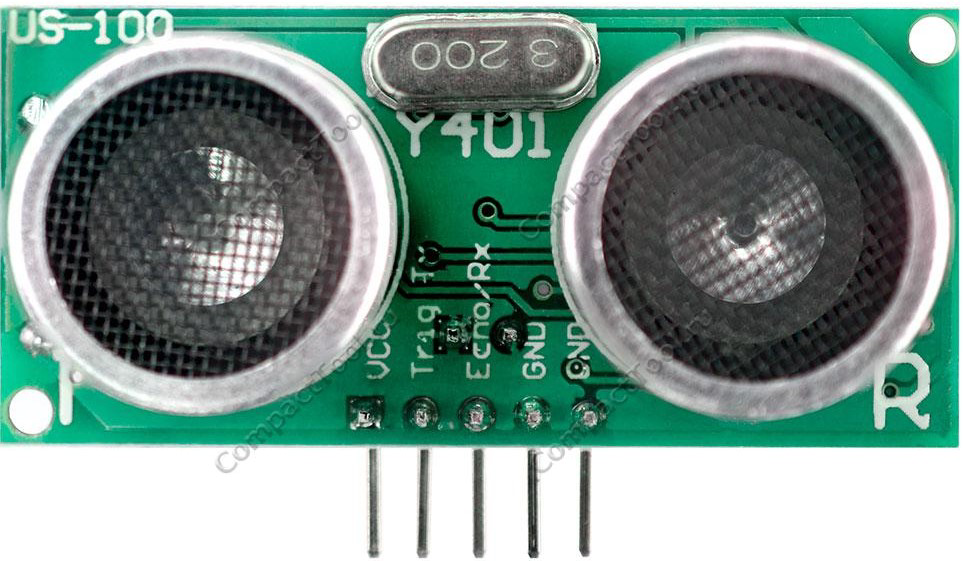
The US100 is a high-performance ultrasonic sensor designed for precise distance measurement and object detection. It operates by emitting ultrasonic waves and calculating the time taken for the echo to return, enabling accurate distance calculations. The US100 is versatile and can operate in both UART (serial) and PWM modes, making it suitable for a wide range of applications.

Explore Projects Built with US100

Use Cirkit Designer to design, explore, and prototype these projects online. Some projects support real-time simulation. Click "Open Project" to start designing instantly!
Satellite-Based Timing and Navigation System with SDR and Atomic Clock Synchronization
Image of GPS 시스템 측정 구성도_Confirm: A project utilizing US100 in a practical application
This circuit appears to be a complex system involving power supply management, GPS and timing synchronization, and data communication. It includes a SI-TEX G1 Satellite Compass for GPS data, an XHTF1021 Atomic Rubidium Clock for precise timing, and Ettus USRP B200 units for software-defined radio communication. Power is supplied through various SMPS units and distributed via terminal blocks and DC jacks. Data communication is facilitated by Beelink MINI S12 N95 computers, RS232 splitters, and a 1000BASE-T Media Converter for network connectivity. RF Directional Couplers are used to interface antennas with the USRP units, and the entire system is likely contained within cases for protection and organization.
Cirkit Designer LogoOpen Project in Cirkit Designer
Battery-Powered Emergency Alert System with NUCLEO-F072RB, SIM800L, and GPS NEO 6M
Image of women safety: A project utilizing US100 in a practical application
This circuit is an emergency alert system that uses a NUCLEO-F072RB microcontroller to send SMS alerts and make calls via a SIM800L GSM module, while obtaining location data from a GPS NEO 6M module. The system is powered by a Li-ion battery and includes a TP4056 module for battery charging and protection, with a rocker switch to control power to the microcontroller.
Cirkit Designer LogoOpen Project in Cirkit Designer
Battery-Powered UPS with Step-Down Buck Converter and BMS
Image of Mini ups: A project utilizing US100 in a practical application
This circuit is a power management system that steps down a 240V AC input to a lower DC voltage using a buck converter, which then powers a 40W UPS. The UPS is controlled by a rocker switch and is backed up by a battery management system (BMS) connected to three 3.7V batteries in series, ensuring continuous power supply.
Cirkit Designer LogoOpen Project in Cirkit Designer
Satellite Compass and Network-Integrated GPS Data Processing System
Image of GPS 시스템 측정 구성도_241016: A project utilizing US100 in a practical application
This circuit comprises a satellite compass, a mini PC, two GPS antennas, power supplies, a network switch, media converters, and an atomic rubidium clock. The satellite compass is powered by a triple output DC power supply and interfaces with an RS232 splitter for 1PPS signals. The mini PCs are connected to the USRP B200 devices via USB for data and power, and to media converters via Ethernet, which in turn connect to a network switch using fiber optic links. The antennas are connected to the USRP B200s through RF directional couplers, and the atomic clock provides a 1PPS input to the RS232 splitter.
Cirkit Designer LogoOpen Project in Cirkit Designer

Explore Projects Built with US100

Use Cirkit Designer to design, explore, and prototype these projects online. Some projects support real-time simulation. Click "Open Project" to start designing instantly!
Image of GPS 시스템 측정 구성도_Confirm: A project utilizing US100 in a practical application
Satellite-Based Timing and Navigation System with SDR and Atomic Clock Synchronization
This circuit appears to be a complex system involving power supply management, GPS and timing synchronization, and data communication. It includes a SI-TEX G1 Satellite Compass for GPS data, an XHTF1021 Atomic Rubidium Clock for precise timing, and Ettus USRP B200 units for software-defined radio communication. Power is supplied through various SMPS units and distributed via terminal blocks and DC jacks. Data communication is facilitated by Beelink MINI S12 N95 computers, RS232 splitters, and a 1000BASE-T Media Converter for network connectivity. RF Directional Couplers are used to interface antennas with the USRP units, and the entire system is likely contained within cases for protection and organization.
Cirkit Designer LogoOpen Project in Cirkit Designer
Image of women safety: A project utilizing US100 in a practical application
Battery-Powered Emergency Alert System with NUCLEO-F072RB, SIM800L, and GPS NEO 6M
This circuit is an emergency alert system that uses a NUCLEO-F072RB microcontroller to send SMS alerts and make calls via a SIM800L GSM module, while obtaining location data from a GPS NEO 6M module. The system is powered by a Li-ion battery and includes a TP4056 module for battery charging and protection, with a rocker switch to control power to the microcontroller.
Cirkit Designer LogoOpen Project in Cirkit Designer
Image of Mini ups: A project utilizing US100 in a practical application
Battery-Powered UPS with Step-Down Buck Converter and BMS
This circuit is a power management system that steps down a 240V AC input to a lower DC voltage using a buck converter, which then powers a 40W UPS. The UPS is controlled by a rocker switch and is backed up by a battery management system (BMS) connected to three 3.7V batteries in series, ensuring continuous power supply.
Cirkit Designer LogoOpen Project in Cirkit Designer
Image of GPS 시스템 측정 구성도_241016: A project utilizing US100 in a practical application
Satellite Compass and Network-Integrated GPS Data Processing System
This circuit comprises a satellite compass, a mini PC, two GPS antennas, power supplies, a network switch, media converters, and an atomic rubidium clock. The satellite compass is powered by a triple output DC power supply and interfaces with an RS232 splitter for 1PPS signals. The mini PCs are connected to the USRP B200 devices via USB for data and power, and to media converters via Ethernet, which in turn connect to a network switch using fiber optic links. The antennas are connected to the USRP B200s through RF directional couplers, and the atomic clock provides a 1PPS input to the RS232 splitter.
Cirkit Designer LogoOpen Project in Cirkit Designer

Common Applications

  • Robotics for obstacle detection and avoidance
  • Distance measurement in automation systems
  • Liquid level sensing in tanks
  • Proximity detection in security systems
  • Smart parking systems for vehicle detection

Technical Specifications

The US100 ultrasonic sensor is equipped with advanced features for reliable and accurate performance. Below are its key technical details:

Parameter Specification
Operating Voltage 2.4V to 5.5V
Operating Current ≤ 2mA
Measuring Range 2cm to 450cm
Measuring Accuracy ±0.3cm
Operating Modes UART (serial) and PWM
Communication Protocol UART: 9600 baud rate
Operating Temperature -20°C to +70°C
Dimensions 45mm x 20mm x 15mm

Pin Configuration

The US100 sensor has four pins, as described in the table below:

Pin Name Description
1 VCC Power supply input (2.4V to 5.5V)
2 GND Ground connection
3 TX UART transmit pin (used for serial communication)
4 RX UART receive pin (used for serial communication)

Usage Instructions

The US100 sensor can be used in either UART or PWM mode. Below are the steps and considerations for using the sensor in a circuit.

Using the US100 in UART Mode

  1. Wiring: Connect the VCC and GND pins to the power supply. Connect the TX and RX pins to the corresponding UART pins on your microcontroller (e.g., Arduino).
  2. Communication: The sensor communicates at a baud rate of 9600. It sends distance data in millimeters when queried.
  3. Query Command: To request a distance measurement, send the command 0x55 to the sensor via the RX pin.

Example Code for Arduino UNO

// US100 Ultrasonic Sensor - UART Mode Example
// This code reads distance data from the US100 sensor and prints it to the Serial Monitor.

#include <SoftwareSerial.h>

// Define the RX and TX pins for SoftwareSerial
SoftwareSerial us100(10, 11); // RX = Pin 10, TX = Pin 11

void setup() {
  Serial.begin(9600);          // Initialize Serial Monitor at 9600 baud
  us100.begin(9600);           // Initialize US100 communication at 9600 baud
  Serial.println("US100 Sensor Initialized");
}

void loop() {
  us100.write(0x55);           // Send query command to the US100 sensor
  delay(100);                  // Wait for the sensor to process the command

  if (us100.available() >= 2) { // Check if at least 2 bytes are available
    uint8_t highByte = us100.read(); // Read the high byte of the distance
    uint8_t lowByte = us100.read();  // Read the low byte of the distance
    int distance = (highByte << 8) | lowByte; // Combine bytes into a 16-bit value

    Serial.print("Distance: ");
    Serial.print(distance);
    Serial.println(" mm");
  } else {
    Serial.println("No data received from US100 sensor");
  }

  delay(500);                  // Wait before the next measurement
}

Using the US100 in PWM Mode

  1. Wiring: Connect the VCC and GND pins to the power supply. The TX pin outputs a PWM signal representing the measured distance.
  2. PWM Signal: The duration of the high pulse corresponds to the measured distance in microseconds. For example, a 1000µs pulse represents a distance of 1000mm.
  3. Reading the Signal: Use a microcontroller to measure the pulse width of the TX pin.

Important Considerations

  • Ensure the sensor is powered within its operating voltage range (2.4V to 5.5V).
  • Avoid placing objects too close to the sensor (<2cm), as it may not provide accurate readings.
  • Use decoupling capacitors near the power supply pins to reduce noise and improve stability.

Troubleshooting and FAQs

Common Issues and Solutions

  1. No Data Received in UART Mode

    • Cause: Incorrect wiring or baud rate mismatch.
    • Solution: Verify the TX and RX connections. Ensure the baud rate is set to 9600.
  2. Inaccurate Distance Measurements

    • Cause: Objects are too close or outside the sensor's range.
    • Solution: Ensure the object is within the 2cm to 450cm range. Avoid reflective or irregular surfaces.
  3. Sensor Not Responding

    • Cause: Insufficient power supply or loose connections.
    • Solution: Check the power supply voltage and ensure all connections are secure.
  4. PWM Signal Not Detected

    • Cause: Incorrect pin configuration or measurement method.
    • Solution: Verify the TX pin is connected to the correct input pin on the microcontroller. Use a pulse-width measurement function.

FAQs

Q1: Can the US100 operate in both UART and PWM modes simultaneously?
A1: No, the US100 operates in either UART or PWM mode. You must configure your circuit for the desired mode.

Q2: What is the maximum distance the US100 can measure?
A2: The US100 can measure distances up to 450cm with an accuracy of ±0.3cm.

Q3: Can the US100 be used outdoors?
A3: While the US100 can operate in a wide temperature range (-20°C to +70°C), it is not waterproof. Use a protective enclosure for outdoor applications.

Q4: How do I switch between UART and PWM modes?
A4: The US100 defaults to UART mode. To use PWM mode, configure your circuit to read the PWM signal from the TX pin.

By following this documentation, you can effectively integrate the US100 ultrasonic sensor into your projects for reliable distance measurement and object detection.