How to Use Outlet: Examples, Pinouts, and Specs
Introduction
An outlet, also known as a power socket or receptacle, is a device that provides a connection point for electrical appliances to access the power supply. Outlets are essential components in residential, commercial, and industrial electrical systems, enabling the safe and convenient transfer of electrical energy to power various devices.
Explore Projects Built with Outlet


Explore Projects Built with Outlet
Common Applications and Use Cases
- Powering household appliances such as refrigerators, televisions, and lamps.
- Providing electricity to office equipment like computers, printers, and monitors.
- Supporting industrial machinery and tools in workshops and factories.
- Charging portable devices such as smartphones, tablets, and laptops.
Technical Specifications
Outlets come in various types and configurations depending on the region, voltage, and current requirements. Below are the general technical specifications for a standard outlet:
General Specifications
| Parameter | Value |
|---|---|
| Voltage Rating | 110-120V AC (North America) |
| 220-240V AC (Europe, Asia, etc.) | |
| Current Rating | 10A, 15A, or 20A (varies by type) |
| Frequency | 50Hz or 60Hz |
| Number of Pins | 2 or 3 (depending on grounding) |
| Grounding | Yes (for 3-pin outlets) |
| Material | Flame-retardant plastic, metal |
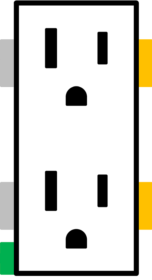
Pin Configuration and Descriptions
Example: Standard North American 3-Pin Outlet
| Pin Name | Description |
|---|---|
| Hot (Live) | Carries the current from the power source. |
| Neutral | Returns the current to the power source. |
| Ground | Provides a safety path for fault currents. |
Example: European Schuko Outlet
| Pin Name | Description |
|---|---|
| Line (L) | Carries the current from the power source. |
| Neutral (N) | Returns the current to the power source. |
| Ground | Metal contacts on the sides for safety grounding. |
Usage Instructions
How to Use the Outlet in a Circuit
- Installation: Ensure the outlet is installed by a qualified electrician. It must be connected to the appropriate circuit breaker and wiring system.
- Connecting Devices: Plug the device's power cord into the outlet. Ensure the plug matches the outlet type and voltage rating.
- Grounding: For safety, always use grounded outlets for devices with a 3-pin plug. This reduces the risk of electric shock.
- Load Capacity: Do not exceed the outlet's current rating. Overloading can cause overheating and potential fire hazards.
Important Considerations and Best Practices
- Voltage Compatibility: Verify that the device's voltage rating matches the outlet's voltage.
- Surge Protection: Use surge protectors to safeguard sensitive electronics from voltage spikes.
- Moisture Protection: Avoid using outlets in wet or damp environments unless they are GFCI (Ground Fault Circuit Interrupter) outlets.
- Regular Inspection: Periodically check outlets for signs of wear, damage, or loose connections.
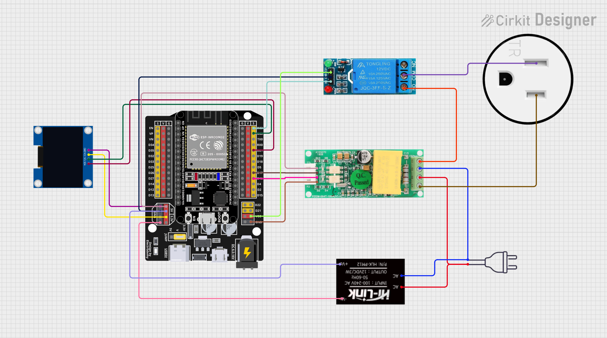
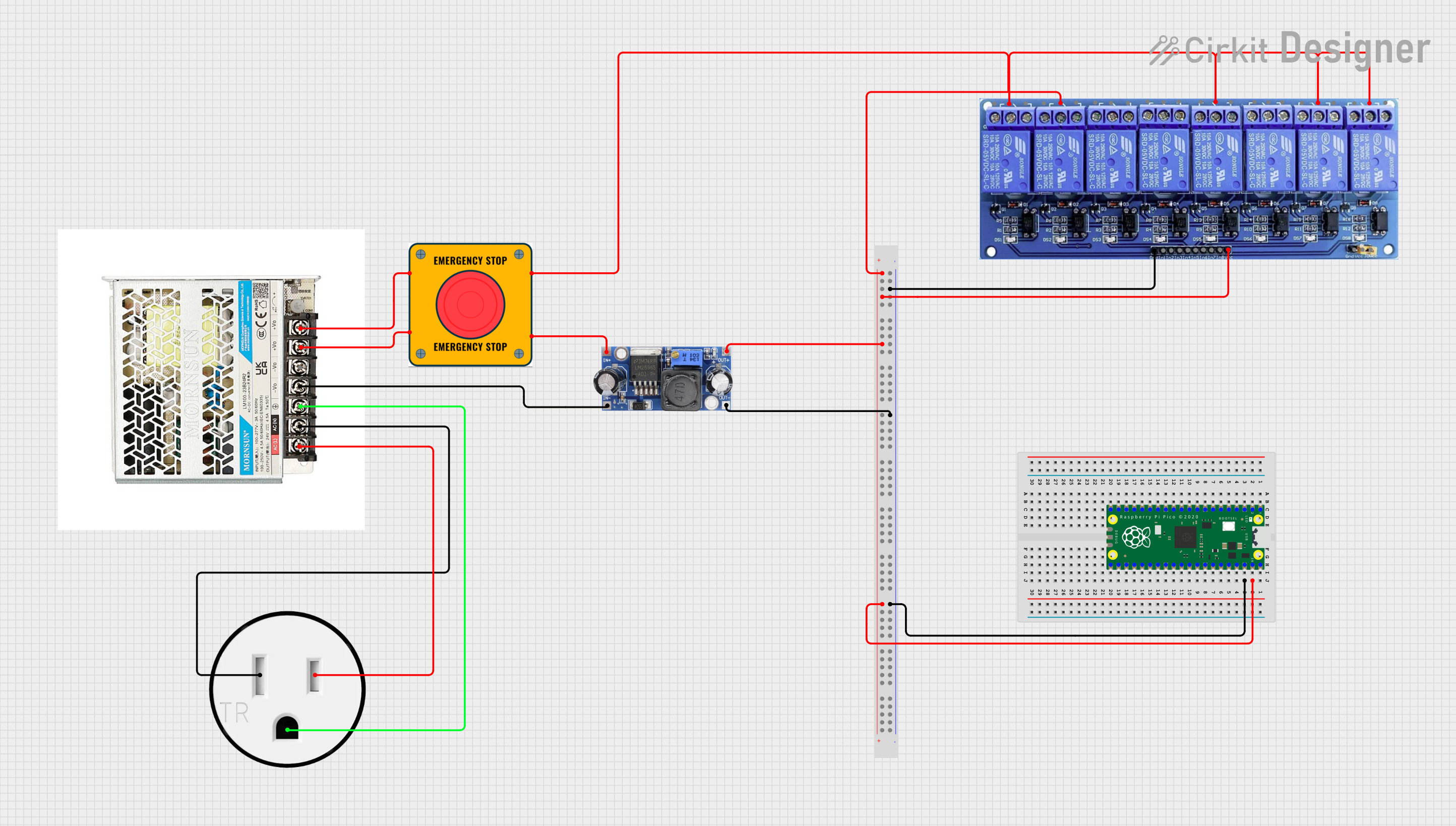
Example: Controlling an Outlet with an Arduino UNO
You can use a relay module to control an outlet with an Arduino UNO. Below is an example code snippet:
/*
  Example: Controlling an Outlet with Arduino and Relay
  This code demonstrates how to use a relay module to control an outlet.
  WARNING: Ensure proper safety precautions when working with high voltage.
*/

const int relayPin = 7; // Pin connected to the relay module

void setup() {
  pinMode(relayPin, OUTPUT); // Set relay pin as output
  digitalWrite(relayPin, LOW); // Ensure relay is off at startup
}

void loop() {
  digitalWrite(relayPin, HIGH); // Turn on the relay (activates outlet)
  delay(5000); // Keep the outlet on for 5 seconds
  digitalWrite(relayPin, LOW); // Turn off the relay (deactivates outlet)
  delay(5000); // Keep the outlet off for 5 seconds
}
Note: Always use a relay module rated for the voltage and current of the outlet. Never directly connect the Arduino to high-voltage components.
Troubleshooting and FAQs
Common Issues and Solutions
Outlet Not Providing Power:
- Cause: Loose wiring or tripped circuit breaker.
- Solution: Check the circuit breaker and ensure proper wiring connections.
Device Not Fitting into Outlet:
- Cause: Mismatched plug and outlet type.
- Solution: Use an appropriate adapter or replace the outlet with a compatible type.
Overheating Outlet:
- Cause: Overloaded circuit or damaged outlet.
- Solution: Reduce the load on the outlet and replace it if damaged.
Frequent Tripping of Circuit Breaker:
- Cause: Overloaded circuit or short circuit.
- Solution: Identify and reduce the load or inspect for wiring faults.
FAQs
Q: Can I use a 110V device with a 220V outlet?
A: No, using a mismatched voltage can damage the device. Use a voltage converter if necessary.
Q: What is the purpose of the ground pin?
A: The ground pin provides a safety path for fault currents, reducing the risk of electric shock.
Q: How do I know if an outlet is overloaded?
A: Signs of overloading include warm outlet surfaces, tripped breakers, or flickering lights. Reduce the load immediately.
Q: Can I install an outlet myself?
A: It is recommended to hire a licensed electrician to ensure safe and code-compliant installation.