How to Use Adjustable Frequency Drives: Examples, Pinouts, and Specs
Introduction
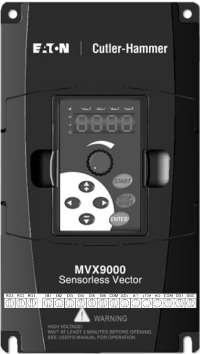
Adjustable Frequency Drives (AFDs), also known as Variable Frequency Drives (VFDs), are devices designed to control the speed and torque of electric motors by varying the frequency and voltage of the power supplied to the motor. The Eaton MVX9000 series is a robust and versatile AFD, suitable for a wide range of industrial and commercial applications. These drives are particularly effective in optimizing energy consumption, improving motor performance, and extending the lifespan of motor systems.
Explore Projects Built with Adjustable Frequency Drives
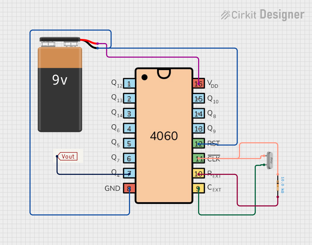
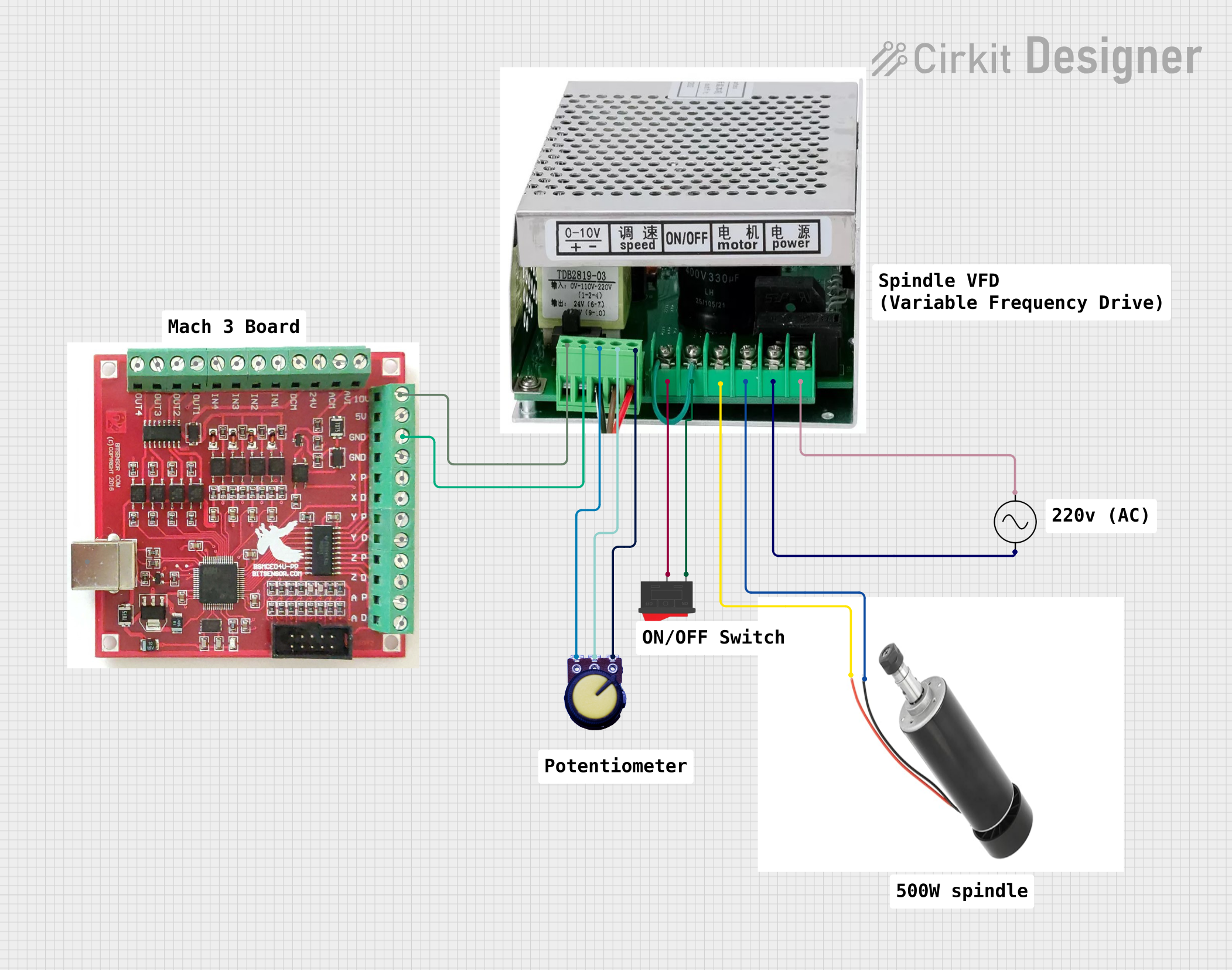
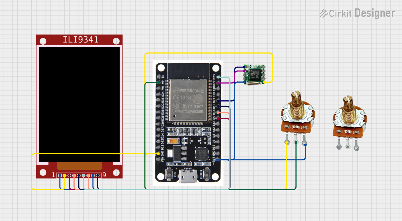
Explore Projects Built with Adjustable Frequency Drives
Common Applications and Use Cases
- HVAC systems for controlling fan and pump speeds
- Conveyor systems in manufacturing plants
- Industrial machinery requiring precise motor control
- Water and wastewater treatment facilities
- Energy-saving retrofits for existing motor systems
Technical Specifications
The Eaton MVX9000 series is designed to meet the demands of modern motor control applications. Below are the key technical specifications:
General Specifications
| Parameter | Value |
|---|---|
| Input Voltage Range | 200-240V AC (Single/Three-phase) |
| Output Voltage Range | 0-240V AC |
| Frequency Range | 0.1 Hz to 400 Hz |
| Power Ratings | 0.5 HP to 30 HP |
| Control Method | V/Hz (Volts per Hertz), Sensorless Vector |
| Efficiency | >95% |
| Operating Temperature | -10°C to 50°C |
| Protection Rating | IP20 (Standard) |
Pin Configuration and Descriptions
The MVX9000 series features a terminal block for control and power connections. Below is the pin configuration:
Control Terminal Block
| Pin No. | Label | Description |
|---|---|---|
| 1 | +24V | 24V DC supply for external devices |
| 2 | COM | Common ground for control signals |
| 3 | FWD | Forward run command input |
| 4 | REV | Reverse run command input |
| 5 | AI1 | Analog input 1 (0-10V DC or 4-20mA) |
| 6 | AO1 | Analog output 1 (0-10V DC, proportional to speed) |
| 7 | DI1 | Digital input 1 (programmable) |
| 8 | DI2 | Digital input 2 (programmable) |
| 9 | DO1 | Digital output 1 (programmable relay) |
Power Terminal Block
| Pin No. | Label | Description |
|---|---|---|
| L1, L2, L3 | Input | AC power input terminals (Single/Three-phase) |
| U, V, W | Output | Motor connection terminals |
| PE | Ground | Protective earth terminal |
Usage Instructions
How to Use the MVX9000 in a Circuit
Wiring the Drive:
- Connect the AC power supply to the input terminals (L1, L2, L3).
- Connect the motor leads to the output terminals (U, V, W).
- Ensure the protective earth (PE) is properly grounded.
- Wire the control signals to the appropriate control terminals based on your application.
Configuring the Drive:
- Power on the drive and access the built-in keypad or connect to a PC using Eaton's configuration software.
- Set the motor parameters (e.g., rated voltage, current, frequency) in the drive's settings.
- Configure the control method (e.g., V/Hz or Sensorless Vector) and input/output functions.
Testing the System:
- Run the motor in forward and reverse directions to verify proper operation.
- Monitor the analog output (AO1) to ensure it reflects the motor speed.
Programming with an Arduino UNO (Optional):
- The MVX9000 can be controlled via analog or digital signals from an Arduino UNO. Below is an example code snippet for controlling motor speed using a PWM signal:
// Arduino code to control Eaton MVX9000 via PWM signal
const int pwmPin = 9; // PWM output pin connected to AI1 on MVX9000

void setup() {
  pinMode(pwmPin, OUTPUT); // Set PWM pin as output
}

void loop() {
  int speed = 128; // Set motor speed (0-255, where 255 is max speed)
  analogWrite(pwmPin, speed); // Send PWM signal to control motor speed
  delay(1000); // Wait for 1 second
}
Important Considerations and Best Practices
- Always ensure the drive is properly grounded to prevent electrical hazards.
- Use shielded cables for control signals to minimize electromagnetic interference (EMI).
- Avoid exceeding the rated voltage, current, and frequency limits of the drive.
- Regularly inspect and clean the drive to prevent dust accumulation and overheating.
Troubleshooting and FAQs
Common Issues and Solutions
Issue: Drive does not power on.
- Solution: Check the input power supply and ensure proper wiring to the L1, L2, and L3 terminals.
Issue: Motor does not start or runs erratically.
- Solution: Verify the control signal wiring and ensure the correct parameters are set in the drive.
Issue: Overcurrent or overvoltage fault.
- Solution: Check the motor connections and ensure the motor is not overloaded. Reduce the acceleration time if necessary.
Issue: Excessive noise or vibration in the motor.
- Solution: Ensure the motor is properly aligned and balanced. Check for loose connections.
FAQs
Q1: Can the MVX9000 be used with single-phase motors?
A1: The MVX9000 is primarily designed for three-phase motors, but it can support single-phase input for certain models. Refer to the specific model's datasheet for compatibility.
Q2: What is the maximum cable length between the drive and the motor?
A2: The maximum cable length depends on the motor's power rating and the cable type. Typically, it is recommended to keep the cable length below 50 meters to minimize voltage drop and EMI.
Q3: Can I use the MVX9000 for regenerative braking?
A3: Yes, the MVX9000 supports regenerative braking with the addition of an external braking resistor.
Q4: How do I reset the drive to factory settings?
A4: Access the drive's menu via the keypad or software and select the "Factory Reset" option under the system settings.
By following this documentation, users can effectively utilize the Eaton MVX9000 Adjustable Frequency Drive for their motor control applications.