Cirkit Designer Logo
Cirkit Designer
Your all-in-one circuit design IDE
Home / 
Component Documentation

How to Use VNH2SP30: Examples, Pinouts, and Specs

Image of VNH2SP30
Cirkit Designer LogoDesign with VNH2SP30 in Cirkit Designer

Introduction

The VNH2SP30 is a full-bridge motor driver integrated circuit (IC) designed for driving high-power DC motors. It is capable of delivering a continuous current of up to 14A and can handle peak currents up to 30A. This IC is well-suited for applications in robotics, automotive, and industrial automation where precise and efficient motor control is required. Its built-in protection features make it a robust and reliable choice for engineers and hobbyists alike.

Explore Projects Built with VNH2SP30

Use Cirkit Designer to design, explore, and prototype these projects online. Some projects support real-time simulation. Click "Open Project" to start designing instantly!
ESP32-Based Smart Irrigation and Environmental Monitoring System
Image of Skripsi: A project utilizing VNH2SP30 in a practical application
This is an automated environmental control system for plant growth that uses an ESP32 to monitor soil moisture and pH levels, and to manage irrigation through solenoid valves. The system aims to maintain optimal growing conditions by adjusting watering schedules based on sensor inputs.
Cirkit Designer LogoOpen Project in Cirkit Designer
ESP32-Based Smart Soil Monitoring System with Wi-Fi Connectivity
Image of Copy of AgriArena project#2K24: A project utilizing VNH2SP30 in a practical application
This circuit is a smart agricultural monitoring system that uses an ESP32 microcontroller to collect data from various sensors, including a DHT22 for temperature and humidity, a pH sensor, an NPK soil sensor, and a capacitive soil moisture sensor. The collected data is displayed on a 0.96" OLED screen, and the RS485 module facilitates communication with the NPK soil sensor.
Cirkit Designer LogoOpen Project in Cirkit Designer
ESP32-Based Smart Agriculture Monitoring System with RS485 Communication
Image of AgriArena project#2K24: A project utilizing VNH2SP30 in a practical application
This circuit features an ESP32 microcontroller interfaced with various sensors including a pH sensor, DHT22 temperature and humidity sensor, capacitive soil moisture sensor, and an NPK soil sensor for monitoring environmental and soil conditions. The ESP32 also connects to an RS485 transceiver for communication and a 0.96" OLED display for output. Power regulation is managed by two 7808 voltage regulators, and the entire system is powered by a single power supply unit.
Cirkit Designer LogoOpen Project in Cirkit Designer
ESP32-Based Environmental Monitoring System with Multiple Sensors and OLED Display
Image of meat_spoilage: A project utilizing VNH2SP30 in a practical application
This circuit is an environmental monitoring system that uses an ESP32 microcontroller to collect data from various sensors, including gas sensors (MQ-135, MQ-136), a humidity and temperature sensor (DHT11), a VOC and NOx sensor (SGP41), and a color sensor (TCS230). The collected data is displayed on an OLED screen and can be transmitted via Bluetooth, with the ESP32 also handling RF signal decoding and transmission.
Cirkit Designer LogoOpen Project in Cirkit Designer

Explore Projects Built with VNH2SP30

Use Cirkit Designer to design, explore, and prototype these projects online. Some projects support real-time simulation. Click "Open Project" to start designing instantly!
Image of Skripsi: A project utilizing VNH2SP30 in a practical application
ESP32-Based Smart Irrigation and Environmental Monitoring System
This is an automated environmental control system for plant growth that uses an ESP32 to monitor soil moisture and pH levels, and to manage irrigation through solenoid valves. The system aims to maintain optimal growing conditions by adjusting watering schedules based on sensor inputs.
Cirkit Designer LogoOpen Project in Cirkit Designer
Image of Copy of AgriArena project#2K24: A project utilizing VNH2SP30 in a practical application
ESP32-Based Smart Soil Monitoring System with Wi-Fi Connectivity
This circuit is a smart agricultural monitoring system that uses an ESP32 microcontroller to collect data from various sensors, including a DHT22 for temperature and humidity, a pH sensor, an NPK soil sensor, and a capacitive soil moisture sensor. The collected data is displayed on a 0.96" OLED screen, and the RS485 module facilitates communication with the NPK soil sensor.
Cirkit Designer LogoOpen Project in Cirkit Designer
Image of AgriArena project#2K24: A project utilizing VNH2SP30 in a practical application
ESP32-Based Smart Agriculture Monitoring System with RS485 Communication
This circuit features an ESP32 microcontroller interfaced with various sensors including a pH sensor, DHT22 temperature and humidity sensor, capacitive soil moisture sensor, and an NPK soil sensor for monitoring environmental and soil conditions. The ESP32 also connects to an RS485 transceiver for communication and a 0.96" OLED display for output. Power regulation is managed by two 7808 voltage regulators, and the entire system is powered by a single power supply unit.
Cirkit Designer LogoOpen Project in Cirkit Designer
Image of meat_spoilage: A project utilizing VNH2SP30 in a practical application
ESP32-Based Environmental Monitoring System with Multiple Sensors and OLED Display
This circuit is an environmental monitoring system that uses an ESP32 microcontroller to collect data from various sensors, including gas sensors (MQ-135, MQ-136), a humidity and temperature sensor (DHT11), a VOC and NOx sensor (SGP41), and a color sensor (TCS230). The collected data is displayed on an OLED screen and can be transmitted via Bluetooth, with the ESP32 also handling RF signal decoding and transmission.
Cirkit Designer LogoOpen Project in Cirkit Designer

Common Applications and Use Cases

  • Robotic vehicles and arms
  • Automotive electronic throttle control
  • Industrial automation systems
  • High-power DC motor control applications

Technical Specifications

Key Technical Details

  • Motor Supply Voltage (Vcc): 5.5V to 16V
  • Logic Supply Voltage (Vss): 2.5V to 5.5V
  • Continuous Output Current (Iout): 14A
  • Peak Output Current (Ipeak): 30A (for a few milliseconds)
  • PWM Frequency: Up to 20 kHz

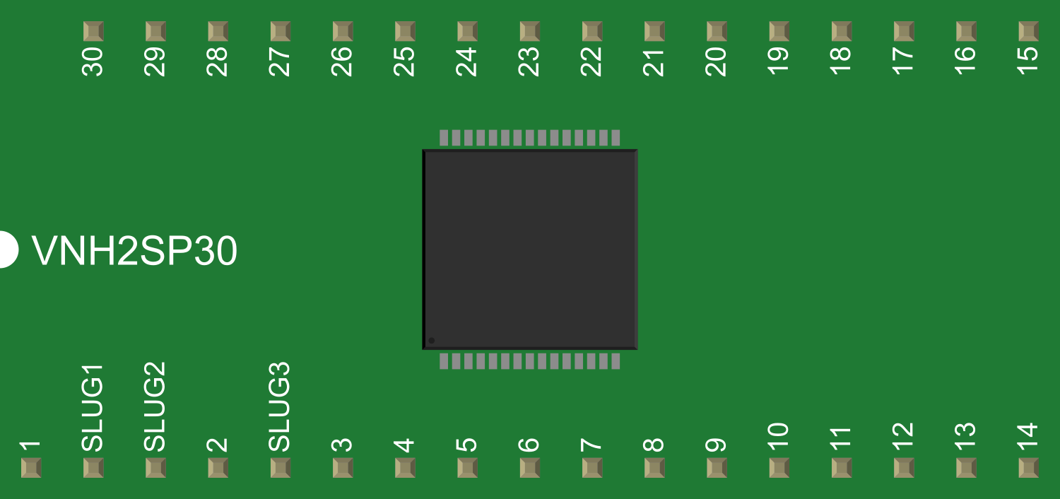
Pin Configuration and Descriptions

Pin Number Pin Name Description
1 Vcc Motor power supply (5.5V to 16V)
2 GND Ground connection
3 INA Input A for PWM and direction control
4 INB Input B for PWM and direction control
5 PWM Pulse Width Modulation input
6 CS Current sense analog output
7 EN Enable input (active high)
8 DIAGA Diagnostic output A
9 DIAGB Diagnostic output B

Usage Instructions

How to Use the Component in a Circuit

  1. Power Connections: Connect the motor supply voltage (Vcc) to pin 1 and ground (GND) to pin 2.
  2. Control Inputs: Connect INA and INB (pins 3 and 4) to your microcontroller or control circuit to set the motor direction.
  3. PWM Input: Apply a PWM signal to the PWM pin (pin 5) to control the speed of the motor.
  4. Enable Pin: Set the EN pin (pin 7) high to enable the driver.
  5. Current Sensing: The CS pin (pin 6) provides an analog voltage proportional to the motor current.
  6. Diagnostics: DIAGA and DIAGB (pins 8 and 9) can be used to monitor the status of the driver and motor.

Important Considerations and Best Practices

  • Ensure that the power supply voltage does not exceed the maximum rating of 16V.
  • Use a proper heat sink to dissipate heat during high current operation.
  • Implement flyback diodes on the motor terminals if inductive loads are used.
  • Avoid running the motor driver at its peak current rating for extended periods to prevent thermal shutdown.
  • Use short and thick wires for motor connections to minimize voltage drops and power losses.

Troubleshooting and FAQs

Common Issues Users Might Face

  • Motor not running: Check power supply connections, ensure the EN pin is set high, and verify that the PWM signal is being applied.
  • Overheating: Make sure a heat sink is attached and that the current does not exceed the continuous rating for extended periods.
  • Erratic motor behavior: Confirm that the input signals (INA, INB, PWM) are clean and without noise.

Solutions and Tips for Troubleshooting

  • Double-check wiring and solder joints for any loose connections or shorts.
  • Use an oscilloscope to examine the control signals for integrity.
  • Ensure that the power supply is capable of delivering the required current for your motor.

FAQs

Q: Can I drive two motors with one VNH2SP30? A: No, the VNH2SP30 is designed to drive one motor. For two motors, you would need two ICs.

Q: What is the maximum PWM frequency I can use? A: The VNH2SP30 can handle PWM frequencies up to 20 kHz.

Q: How do I use the current sense feature? A: The CS pin outputs an analog voltage proportional to the motor current. You can read this voltage with an ADC to monitor the current draw.

Example Code for Arduino UNO

// Define control pins for VNH2SP30
const int inAPin = 2; // INA pin
const int inBPin = 3; // INB pin
const int pwmPin = 5; // PWM pin
const int enPin = 4;  // Enable pin

void setup() {
  // Set control pins as outputs
  pinMode(inAPin, OUTPUT);
  pinMode(inBPin, OUTPUT);
  pinMode(pwmPin, OUTPUT);
  pinMode(enPin, OUTPUT);

  // Enable the motor driver
  digitalWrite(enPin, HIGH);
}

void loop() {
  // Set motor direction to forward
  digitalWrite(inAPin, HIGH);
  digitalWrite(inBPin, LOW);

  // Set motor speed (PWM value 0 to 255)
  analogWrite(pwmPin, 128); // 50% duty cycle

  // Add a delay to see the motor in action
  delay(2000);

  // Change motor direction to reverse
  digitalWrite(inAPin, LOW);
  digitalWrite(inBPin, HIGH);

  // Keep the same motor speed
  delay(2000);
}

Remember to adjust the PWM value to control the speed of the motor and ensure that the control signals do not exceed the logic supply voltage (Vss) limits.