
How to Use 2.4GHz Low Power Transceiver: Examples, Pinouts, and Specs
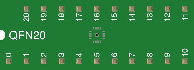
 Design with 2.4GHz Low Power Transceiver in Cirkit Designer
Introduction
The nRF24L01 is a compact 2.4GHz Low Power Transceiver module manufactured by Nordic Semiconductor. It is designed for wireless communication in the 2.4GHz ISM (Industrial, Scientific, and Medical) band. This module is widely used in low-power applications such as Internet of Things (IoT) devices, remote controls, wireless sensors, and home automation systems. Its small size, low power consumption, and robust communication capabilities make it an ideal choice for a variety of wireless applications.
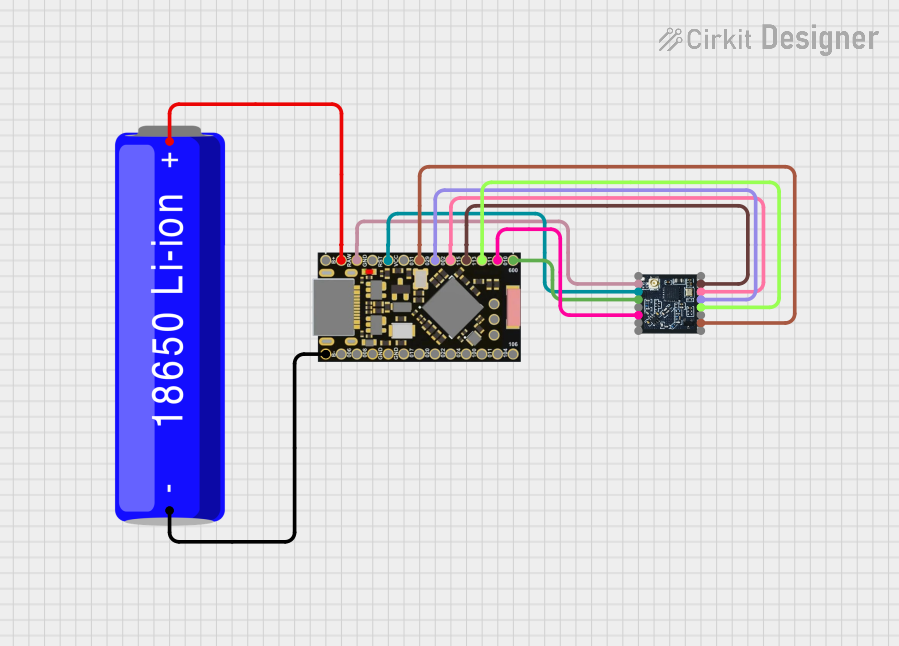
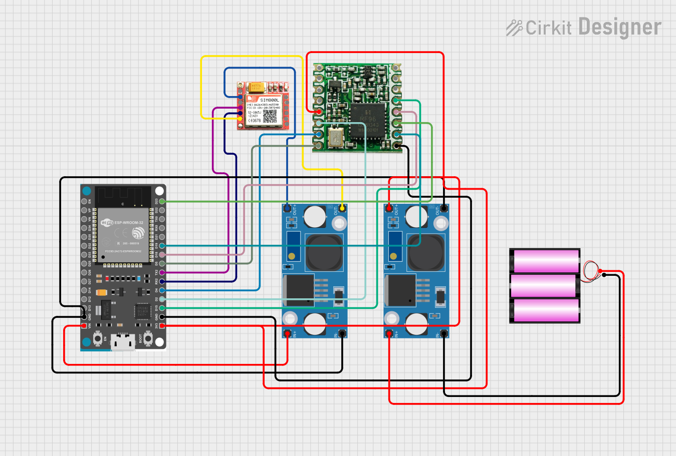
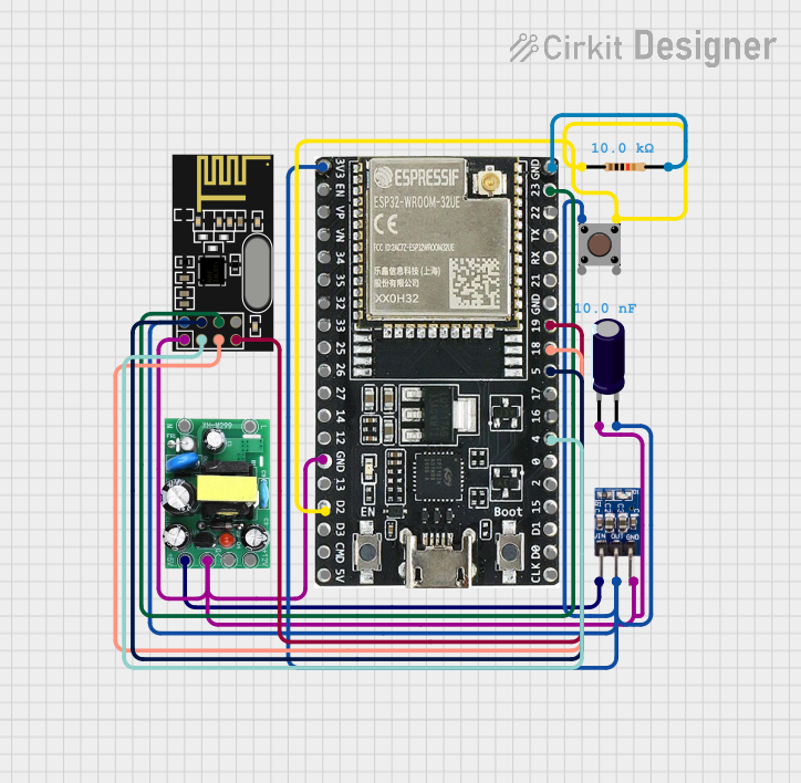
Explore Projects Built with 2.4GHz Low Power Transceiver
 Open Project in Cirkit Designer
 Open Project in Cirkit Designer
 Open Project in Cirkit Designer
 Open Project in Cirkit Designer
Explore Projects Built with 2.4GHz Low Power Transceiver
Open Project in Cirkit DesignerOpen Project in Cirkit DesignerOpen Project in Cirkit DesignerOpen Project in Cirkit DesignerCommon Applications
- Wireless sensor networks
- IoT devices and smart home systems
- Remote controls for drones, toys, and appliances
- Industrial automation and monitoring
- Wireless data transmission between microcontrollers
Technical Specifications
The nRF24L01 module is packed with features that make it versatile and efficient for wireless communication. Below are its key technical specifications:
| Parameter | Value |
|---|---|
| Operating Frequency | 2.4GHz ISM Band |
| Data Rate | 250kbps, 1Mbps, 2Mbps |
| Operating Voltage | 1.9V to 3.6V |
| Current Consumption | 11.3mA (TX at 0dBm), 13.5mA (RX mode) |
| Sleep Mode Current | 900nA |
| Communication Range | Up to 100 meters (line of sight) |
| Modulation Scheme | GFSK (Gaussian Frequency Shift Keying) |
| Number of Channels | 125 |
| SPI Interface Speed | Up to 10Mbps |
| Operating Temperature | -40°C to +85°C |
| Dimensions | 15mm x 29mm |
Pin Configuration
The nRF24L01 module has 8 pins, which are used for power, communication, and control. Below is the pin configuration:
| Pin | Name | Description |
|---|---|---|
| 1 | GND | Ground connection |
| 2 | VCC | Power supply (1.9V to 3.6V) |
| 3 | CE | Chip Enable: Activates RX or TX mode |
| 4 | CSN | Chip Select Not: SPI enable (active low) |
| 5 | SCK | Serial Clock: SPI clock input |
| 6 | MOSI | Master Out Slave In: SPI data input |
| 7 | MISO | Master In Slave Out: SPI data output |
| 8 | IRQ | Interrupt Request: Indicates data ready or status |
Usage Instructions
How to Use the nRF24L01 in a Circuit
- Power Supply: Connect the VCC pin to a 3.3V power source. Do not connect it directly to 5V as it may damage the module. Use a 3.3V regulator if your system operates at 5V.
- SPI Communication: Connect the SPI pins (CSN, SCK, MOSI, MISO) to the corresponding SPI pins on your microcontroller.
- Chip Enable (CE): Use a GPIO pin on your microcontroller to control the CE pin. Set it high to enable transmission or reception.
- Interrupt (IRQ): Optionally, connect the IRQ pin to a GPIO pin on your microcontroller to handle interrupts for data-ready or status changes.
- Antenna: Ensure the module's onboard antenna is unobstructed for optimal signal strength.
Best Practices
- Use decoupling capacitors (e.g., 10µF and 0.1µF) between VCC and GND to stabilize the power supply.
- Keep the module away from metal objects or other RF sources to minimize interference.
- Use a dedicated 3.3V power supply for the module to avoid noise from other components.
Example Code for Arduino UNO
Below is an example of how to use the nRF24L01 module with an Arduino UNO for basic communication:
#include <SPI.h>
#include <nRF24L01.h>
#include <RF24.h>

// Define CE and CSN pins for the nRF24L01 module
#define CE_PIN 9
#define CSN_PIN 10

// Create an RF24 object
RF24 radio(CE_PIN, CSN_PIN);

// Define the address for communication
const byte address[6] = "00001";

void setup() {
  Serial.begin(9600); // Initialize serial communication
  radio.begin();      // Initialize the nRF24L01 module
  radio.openWritingPipe(address); // Set the address for transmission
  radio.setPALevel(RF24_PA_LOW);  // Set power level to low
  radio.stopListening();          // Set module to transmit mode
}

void loop() {
  const char text[] = "Hello, World!"; // Message to send
  bool success = radio.write(&text, sizeof(text)); // Send the message

  if (success) {
    Serial.println("Message sent successfully!");
  } else {
    Serial.println("Message failed to send.");
  }

  delay(1000); // Wait 1 second before sending the next message
}
Notes
- Install the RF24 library in the Arduino IDE before using the code.
- Adjust the CE and CSN pin definitions if using different GPIO pins.
Troubleshooting and FAQs
Common Issues
No Communication Between Modules
- Ensure both modules are using the same address and data rate.
- Verify the wiring, especially the SPI connections.
- Check the power supply voltage (must be 3.3V).
Short Communication Range
- Ensure the antenna is unobstructed and positioned correctly.
- Reduce interference by moving the module away from other RF sources.
Module Not Responding
- Verify that the CE and CSN pins are correctly connected and configured in the code.
- Check for loose connections or damaged components.
FAQs
Q: Can I use the nRF24L01 with a 5V microcontroller?
A: Yes, but you must use a 3.3V regulator for the VCC pin and level shifters for the SPI pins to avoid damaging the module.
Q: What is the maximum range of the nRF24L01?
A: The maximum range is up to 100 meters in line-of-sight conditions. However, obstacles and interference can reduce the range.
Q: How do I increase the communication range?
A: Use the nRF24L01+PA+LNA variant, which includes a power amplifier and low-noise amplifier for extended range.
Q: Can I use multiple nRF24L01 modules in the same network?
A: Yes, the module supports up to 6 data pipes, allowing multiple devices to communicate simultaneously.
By following this documentation, you can effectively integrate the nRF24L01 module into your projects for reliable wireless communication.