How to Use STM 32F407 Discovery Kit: Examples, Pinouts, and Specs
Introduction
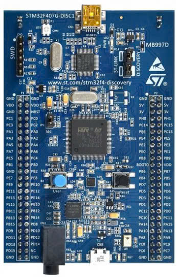
The STM32F407 Discovery Kit is a development board designed by STMicroelectronics to facilitate prototyping and testing of embedded systems. It features the STM32F407 microcontroller, a high-performance ARM Cortex-M4 processor with advanced peripherals and interfaces. This board is ideal for developers working on applications such as motor control, audio processing, industrial automation, and IoT devices.
Explore Projects Built with STM 32F407 Discovery Kit


Explore Projects Built with STM 32F407 Discovery Kit
Common Applications and Use Cases
- Prototyping embedded systems
- Developing IoT applications
- Motor control and robotics
- Audio signal processing
- Industrial automation and control systems
- Educational purposes for learning ARM Cortex-M4 architecture
Technical Specifications
Key Technical Details
- Microcontroller: STM32F407VGT6 (ARM Cortex-M4, 32-bit)
- Clock Speed: Up to 168 MHz
- Flash Memory: 1 MB
- SRAM: 192 KB
- Operating Voltage: 3.3V
- Input Voltage Range: 5V (via USB) or 7-12V (via external power supply)
- Interfaces: USB OTG, USART, SPI, I2C, CAN, and more
- Onboard Peripherals:
- 3-axis accelerometer (LIS302DL or LIS3DSH)
- MEMS microphone
- User and reset push-buttons
- 4 user LEDs
- Debugging: ST-LINK/V2 embedded debugger
- Expansion: 2x 50-pin headers for external connections
Pin Configuration and Descriptions
The STM32F407 Discovery Kit provides access to the microcontroller's pins via two 50-pin headers. Below is a summary of key pins and their functions:
| Pin Name | Function | Description |
|---|---|---|
| VDD | Power Supply | 3.3V power supply for the board |
| GND | Ground | Ground connection |
| PA0-PA15 | GPIO/Analog/Digital I/O | General-purpose I/O pins |
| PB0-PB15 | GPIO/Analog/Digital I/O | General-purpose I/O pins |
| PC0-PC15 | GPIO/Analog/Digital I/O | General-purpose I/O pins |
| PD0-PD15 | GPIO/Analog/Digital I/O | General-purpose I/O pins |
| USART1_TX | UART Transmit | Transmit data via UART |
| USART1_RX | UART Receive | Receive data via UART |
| SPI1_MOSI | SPI Master Out, Slave In | SPI data output |
| SPI1_MISO | SPI Master In, Slave Out | SPI data input |
| SPI1_SCK | SPI Clock | SPI clock signal |
| I2C1_SCL | I2C Clock | I2C clock signal |
| I2C1_SDA | I2C Data | I2C data signal |
| USB_DM | USB Data- | USB differential data line |
| USB_DP | USB Data+ | USB differential data line |
For a complete pinout, refer to the official STM32F407 Discovery Kit datasheet.
Usage Instructions
How to Use the Component in a Circuit
Powering the Board:
- Connect the board to a PC via the USB Mini-B connector for power and programming.
- Alternatively, use an external power supply (7-12V) connected to the VIN and GND pins.
Programming the Microcontroller:
- Use the onboard ST-LINK/V2 debugger to program the STM32F407 microcontroller.
- Compatible IDEs include STM32CubeIDE, Keil MDK, and IAR Embedded Workbench.
Connecting Peripherals:
- Use the GPIO pins to connect external sensors, actuators, or other devices.
- Configure the pins in the software as input, output, or alternate functions (e.g., UART, SPI).
Running the Program:
- After programming, press the reset button to run the application.
- Use the user LEDs and push-buttons for basic input/output testing.
Important Considerations and Best Practices
- Ensure the board is powered within the specified voltage range to avoid damage.
- Use decoupling capacitors when connecting external components to reduce noise.
- Avoid shorting GPIO pins to ground or VDD directly.
- Use proper pull-up or pull-down resistors for input pins to ensure stable operation.
- When using USB OTG, ensure the correct configuration of the USB pins in the software.
Example Code for Arduino UNO Integration
Although the STM32F407 Discovery Kit is not directly compatible with Arduino, it can communicate with an Arduino UNO via UART. Below is an example of how to send data from the STM32F407 to an Arduino UNO:
STM32F407 Code (Using STM32CubeIDE):
#include "stm32f4xx_hal.h"

UART_HandleTypeDef huart1; // UART handle for USART1

void SystemClock_Config(void);
void MX_USART1_UART_Init(void);

int main(void) {
    HAL_Init(); // Initialize the HAL library
    SystemClock_Config(); // Configure the system clock
    MX_USART1_UART_Init(); // Initialize UART1

    char message[] = "Hello from STM32F407!\r\n";

    while (1) {
        HAL_UART_Transmit(&huart1, (uint8_t *)message, sizeof(message) - 1, HAL_MAX_DELAY);
        HAL_Delay(1000); // Wait for 1 second
    }
}

// UART1 initialization function
void MX_USART1_UART_Init(void) {
    huart1.Instance = USART1;
    huart1.Init.BaudRate = 9600;
    huart1.Init.WordLength = UART_WORDLENGTH_8B;
    huart1.Init.StopBits = UART_STOPBITS_1;
    huart1.Init.Parity = UART_PARITY_NONE;
    huart1.Init.Mode = UART_MODE_TX_RX;
    huart1.Init.HwFlowCtl = UART_HWCONTROL_NONE;
    huart1.Init.OverSampling = UART_OVERSAMPLING_16;
    HAL_UART_Init(&huart1);
}
Arduino UNO Code:
void setup() {
    Serial.begin(9600); // Initialize serial communication at 9600 baud
}

void loop() {
    if (Serial.available()) {
        // Read data from STM32F407 and print it to the Serial Monitor
        String data = Serial.readString();
        Serial.println("Received: " + data);
    }
}
Troubleshooting and FAQs
Common Issues and Solutions
Board Not Detected by PC:
- Ensure the USB cable is functional and properly connected.
- Check if the ST-LINK driver is installed on your PC.
Program Not Running:
- Verify that the microcontroller is programmed correctly.
- Press the reset button after programming to start the application.
GPIO Pins Not Responding:
- Ensure the pins are configured correctly in the software.
- Check for short circuits or incorrect connections.
Debugging Not Working:
- Ensure the ST-LINK/V2 debugger is enabled in the IDE settings.
- Update the ST-LINK firmware if necessary.
FAQs
Can I power the board using a battery? Yes, you can use a 3.7V LiPo battery or a 7-12V external power source.
Is the STM32F407 Discovery Kit compatible with Arduino libraries? No, but you can use STM32 HAL or LL libraries to achieve similar functionality.
How do I update the ST-LINK firmware? Use the ST-LINK Utility software provided by STMicroelectronics to update the firmware.
For further assistance, refer to the official STM32F407 Discovery Kit user manual and datasheet.