How to Use PS/2 Keyboard: Examples, Pinouts, and Specs
Introduction
The PS/2 keyboard is a type of input device that connects to a computer via a PS/2 port, utilizing a 6-pin mini-DIN connector. It was widely used in older computer systems for inputting text and commands. Despite being largely replaced by USB keyboards, PS/2 keyboards are still valued in certain applications due to their low latency and direct hardware-level communication.
Explore Projects Built with PS/2 Keyboard


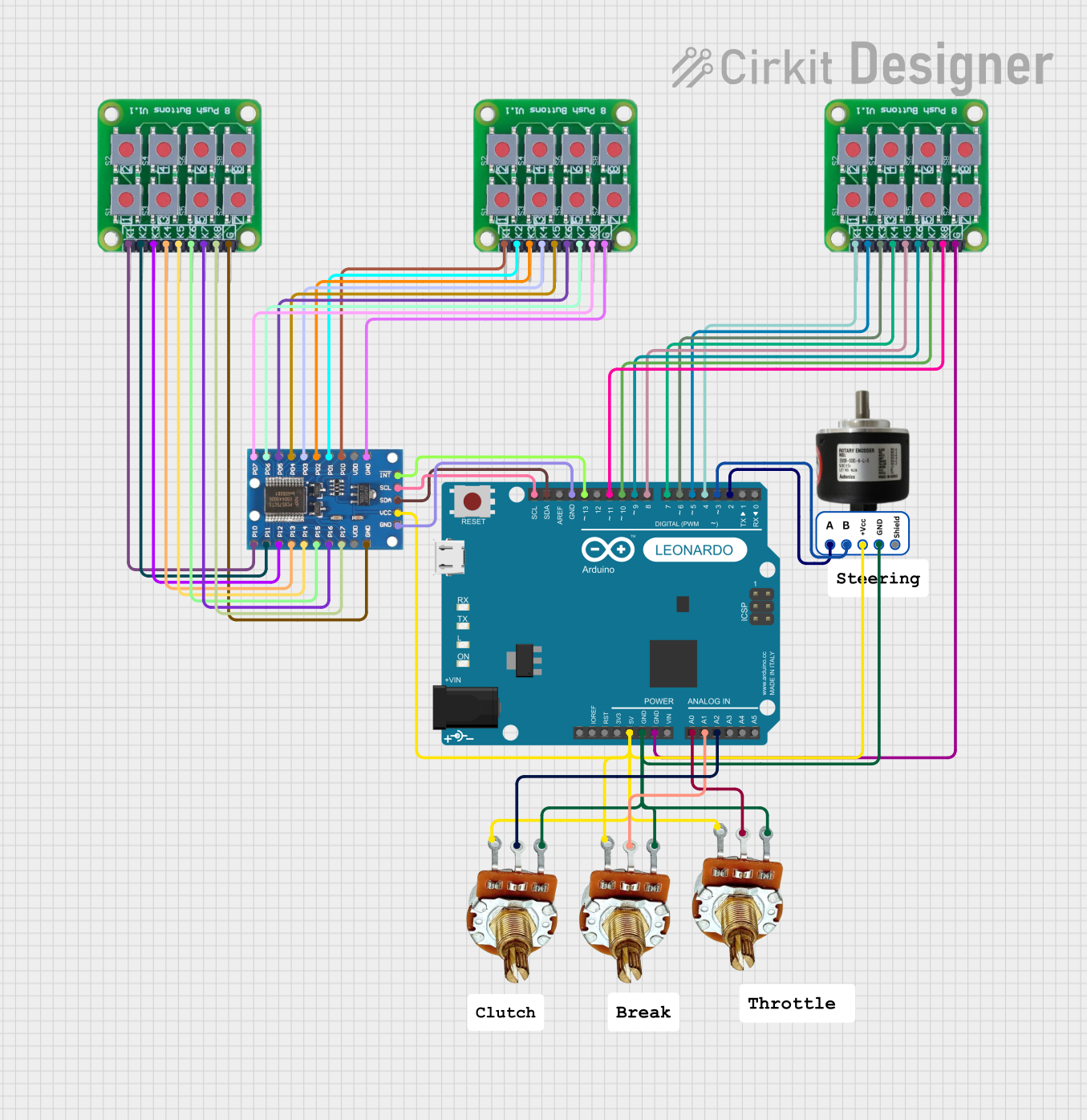
Explore Projects Built with PS/2 Keyboard
Common Applications and Use Cases
- Legacy computer systems and servers
- Embedded systems requiring low-latency input
- Applications where USB ports are unavailable or limited
- Hobbyist and DIY electronics projects, such as interfacing with microcontrollers
Technical Specifications
Key Technical Details
- Connector Type: 6-pin mini-DIN
- Communication Protocol: Bidirectional serial communication
- Voltage: 5V DC (supplied by the host device)
- Current Consumption: Typically 10-25 mA
- Clock Frequency: 10-16 kHz (provided by the keyboard)
- Data Format: 11-bit frame (1 start bit, 8 data bits, 1 parity bit, 1 stop bit)
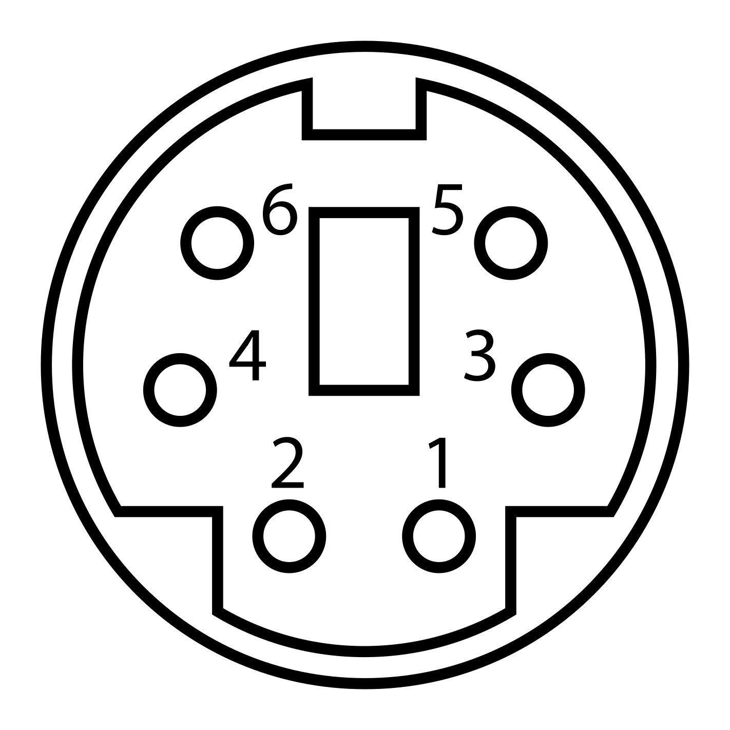
Pin Configuration and Descriptions
The PS/2 connector has six pins, but only four are typically used for communication. Below is the pinout:
| Pin Number | Name | Description |
|---|---|---|
| 1 | Data | Serial data line for communication |
| 2 | Not Connected | Unused |
| 3 | Ground (GND) | Electrical ground |
| 4 | VCC | +5V power supply |
| 5 | Clock | Clock signal generated by the keyboard |
| 6 | Not Connected | Unused |
Usage Instructions
How to Use the PS/2 Keyboard in a Circuit
- Power Supply: Connect the VCC pin (Pin 4) to a 5V power source and the GND pin (Pin 3) to ground.
- Data and Clock Lines: Connect the Data (Pin 1) and Clock (Pin 5) lines to the appropriate GPIO pins on your microcontroller or host device.
- Pull-Up Resistors: Use pull-up resistors (typically 10kΩ) on the Data and Clock lines to ensure proper signal levels.
- Communication Protocol: Implement the PS/2 protocol to read data from the keyboard. The keyboard sends data in an 11-bit frame, which must be decoded by the host.
Important Considerations and Best Practices
- Voltage Levels: Ensure the host device operates at 5V logic levels. If using a 3.3V microcontroller, level shifters may be required.
- Signal Integrity: Keep the Data and Clock lines short to minimize noise and signal degradation.
- Timing: The host must be able to process the keyboard's clock signal (10-16 kHz) in real-time to avoid data loss.
Example: Interfacing a PS/2 Keyboard with Arduino UNO
Below is an example code snippet for reading data from a PS/2 keyboard using an Arduino UNO:
// PS/2 Keyboard Interface Example for Arduino UNO
// Connect Data to pin 2 and Clock to pin 3 on the Arduino

#define DATA_PIN 2  // PS/2 Data line connected to Arduino pin 2
#define CLOCK_PIN 3 // PS/2 Clock line connected to Arduino pin 3

volatile bool dataAvailable = false; // Flag to indicate data is ready
volatile uint8_t receivedData = 0;   // Variable to store received data

void clockISR() {
  static uint8_t bitCount = 0; // Tracks the number of bits received
  static uint8_t dataBuffer = 0; // Temporary buffer for incoming data

  if (bitCount < 8) {
    // Read the data bit (LSB first)
    if (digitalRead(DATA_PIN)) {
      dataBuffer |= (1 << bitCount);
    }
    bitCount++;
  } else if (bitCount == 8) {
    // All 8 data bits received, store the data
    receivedData = dataBuffer;
    dataAvailable = true;
    bitCount = 0; // Reset for the next byte
    dataBuffer = 0;
  }
}

void setup() {
  pinMode(DATA_PIN, INPUT_PULLUP);  // Set Data pin as input with pull-up
  pinMode(CLOCK_PIN, INPUT_PULLUP); // Set Clock pin as input with pull-up

  attachInterrupt(digitalPinToInterrupt(CLOCK_PIN), clockISR, FALLING);
  Serial.begin(9600); // Initialize serial communication for debugging
}

void loop() {
  if (dataAvailable) {
    Serial.print("Received Data: ");
    Serial.println(receivedData, HEX); // Print received data in hexadecimal
    dataAvailable = false; // Reset the flag
  }
}
Notes:
- The above code assumes the keyboard sends data in 8-bit packets. Additional handling may be required for parity and stop bits.
- Ensure the keyboard is properly powered before running the code.
Troubleshooting and FAQs
Common Issues and Solutions
No Data Received:
- Verify the connections to the Data and Clock pins.
- Ensure pull-up resistors are installed on the Data and Clock lines.
- Check that the keyboard is powered (5V on Pin 4).
Garbage Data or Incorrect Characters:
- Ensure the host device is correctly decoding the PS/2 protocol.
- Verify the timing of the clock signal (10-16 kHz).
- Check for noise or interference on the Data and Clock lines.
Keyboard Not Responding:
- Confirm the keyboard is functional by testing it on another device.
- Ensure the host device is providing 5V power to the keyboard.
FAQs
Q: Can I use a PS/2 keyboard with a modern computer?
A: Most modern computers lack PS/2 ports, but you can use a PS/2-to-USB adapter to connect the keyboard.
Q: Why use a PS/2 keyboard instead of USB?
A: PS/2 keyboards offer lower latency and direct hardware-level communication, making them ideal for certain applications.
Q: Can I connect a PS/2 keyboard to a 3.3V microcontroller?
A: Yes, but you will need level shifters to safely interface the 5V signals with the 3.3V microcontroller.