How to Use ESP8285 (01M): Examples, Pinouts, and Specs
Introduction
The ESP8285 is a low-cost Wi-Fi microcontroller with a built-in 1MB flash memory, designed specifically for Internet of Things (IoT) applications. It is based on the ESP8266 architecture but integrates flash memory directly into the chip, making it more compact and reliable for space-constrained designs. The ESP8285 features a 32-bit RISC CPU, supports multiple communication protocols (e.g., UART, SPI, I2C), and is compatible with the Arduino IDE, enabling rapid prototyping and development of connected devices.
Explore Projects Built with ESP8285 (01M)


Explore Projects Built with ESP8285 (01M)
Common Applications and Use Cases
- Smart home devices (e.g., smart plugs, light switches)
- IoT sensors and data loggers
- Wearable devices
- Wireless communication modules
- Industrial automation and monitoring systems
Technical Specifications
Key Technical Details
| Parameter | Value |
|---|---|
| CPU | 32-bit RISC Tensilica L106 |
| Clock Speed | Up to 160 MHz |
| Flash Memory | 1MB (embedded) |
| Operating Voltage | 3.0V - 3.6V |
| Wi-Fi Standard | IEEE 802.11 b/g/n (2.4 GHz) |
| GPIO Pins | Up to 9 GPIOs |
| Communication Interfaces | UART, SPI, I2C, PWM, ADC |
| Power Consumption | 10 µA (deep sleep), ~70 mA (Wi-Fi) |
| Operating Temperature | -40°C to +125°C |
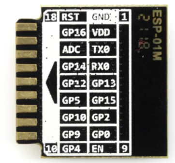
Pin Configuration and Descriptions
The ESP8285 (01M) module typically comes with an 8-pin configuration. Below is the pinout and description:
| Pin Number | Pin Name | Description |
|---|---|---|
| 1 | GND | Ground |
| 2 | TX | UART Transmit (for serial communication) |
| 3 | RX | UART Receive (for serial communication) |
| 4 | GPIO0 | General Purpose I/O, used for boot mode selection |
| 5 | GPIO2 | General Purpose I/O |
| 6 | CH_PD | Chip Enable (active high, must be pulled to 3.3V) |
| 7 | VCC | Power Supply (3.0V - 3.6V) |
| 8 | RST | Reset (active low, used to restart the module) |
Usage Instructions
How to Use the ESP8285 in a Circuit
- Power Supply: Connect the
VCCpin to a 3.3V regulated power source and theGNDpin to ground. Ensure the power supply can provide sufficient current (at least 200 mA). - Enable the Chip: Pull the
CH_PDpin high (connect to 3.3V) to enable the module. - Serial Communication: Use the
TXandRXpins to communicate with a microcontroller or USB-to-serial adapter. Ensure the logic level is 3.3V to avoid damaging the module. - Boot Mode Selection: For normal operation, ensure
GPIO0is pulled high. To flash firmware, pullGPIO0low during power-up or reset. - GPIO Usage: Use the available GPIO pins for interfacing with sensors, actuators, or other peripherals.
Important Considerations and Best Practices
- Voltage Levels: The ESP8285 operates at 3.3V. Avoid applying 5V to any pin, as this may permanently damage the module.
- Decoupling Capacitors: Place a 0.1 µF ceramic capacitor close to the
VCCpin to stabilize the power supply. - Antenna Placement: Ensure the onboard antenna is not obstructed by metal objects or PCB traces to maintain good Wi-Fi signal strength.
- Firmware Updates: Use the Arduino IDE or ESP8266 toolchain to upload firmware. Ensure the correct board settings are selected in the IDE.
Example: Connecting ESP8285 to Arduino UNO
Below is an example of how to connect the ESP8285 to an Arduino UNO and send a basic AT command:
Wiring Diagram
| ESP8285 Pin | Arduino UNO Pin |
|---|---|
| VCC | 3.3V |
| GND | GND |
| TX | Pin 10 (via voltage divider) |
| RX | Pin 11 |
| CH_PD | 3.3V |
| GPIO0 | 3.3V |
Arduino Code
#include <SoftwareSerial.h>

// Define RX and TX pins for SoftwareSerial
SoftwareSerial espSerial(10, 11); // RX, TX

void setup() {
  Serial.begin(9600); // Initialize Serial Monitor
  espSerial.begin(9600); // Initialize ESP8285 communication

  Serial.println("ESP8285 Test");
  delay(1000);

  // Send an AT command to test communication
  espSerial.println("AT");
}

void loop() {
  // Check if ESP8285 has sent any data
  if (espSerial.available()) {
    String response = espSerial.readString();
    Serial.println("ESP8285 Response: " + response);
  }

  // Check if user has sent data from Serial Monitor
  if (Serial.available()) {
    String command = Serial.readString();
    espSerial.println(command); // Send command to ESP8285
  }
}
Notes:
- Use a voltage divider or logic level shifter to step down the Arduino's 5V TX signal to 3.3V for the ESP8285's RX pin.
- Ensure the baud rate matches the ESP8285's default setting (usually 9600 or 115200).
Troubleshooting and FAQs
Common Issues and Solutions
No Response to AT Commands
- Ensure the
CH_PDpin is pulled high (3.3V). - Verify the baud rate in the Arduino code matches the ESP8285's default baud rate.
- Check the wiring, especially the TX and RX connections.
- Ensure the
Wi-Fi Connection Fails
- Ensure the Wi-Fi credentials (SSID and password) are correct.
- Check for interference or weak signal strength. Reposition the module if necessary.
Module Overheats
- Verify the power supply voltage is within the 3.0V - 3.6V range.
- Avoid drawing excessive current from GPIO pins.
Firmware Upload Fails
- Ensure
GPIO0is pulled low during power-up or reset to enter bootloader mode. - Use a reliable USB-to-serial adapter with 3.3V logic levels.
- Ensure
FAQs
Q: Can the ESP8285 be programmed using the Arduino IDE?
A: Yes, the ESP8285 is fully compatible with the Arduino IDE. Install the ESP8266 board package to program it.
Q: What is the difference between ESP8285 and ESP8266?
A: The ESP8285 integrates 1MB of flash memory directly into the chip, making it more compact and suitable for space-constrained designs.
Q: Can the ESP8285 operate on 5V?
A: No, the ESP8285 operates at 3.3V. Applying 5V to any pin may damage the module.
Q: How many GPIO pins are available?
A: The ESP8285 provides up to 9 GPIO pins, depending on the module configuration.