Cirkit Designer Logo
Cirkit Designer
Your all-in-one circuit design IDE
Home / 
Component Documentation

How to Use MCP4017T-103E/LT: Examples, Pinouts, and Specs

Image of MCP4017T-103E/LT
Cirkit Designer LogoDesign with MCP4017T-103E/LT in Cirkit Designer

Introduction

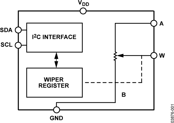
The MCP4017T-103E/LT is a digital potentiometer manufactured by Microchip Technology Inc. It features a resistance value of 10 kΩ and a 7-bit resolution, allowing for 128 discrete resistance steps. This component is controlled via a simple 2-wire I2C interface, making it ideal for applications requiring precise, adjustable resistance in a compact and efficient form factor.

Explore Projects Built with MCP4017T-103E/LT

Use Cirkit Designer to design, explore, and prototype these projects online. Some projects support real-time simulation. Click "Open Project" to start designing instantly!
I2C-Controlled Relay Switching with ESP32 and MCP23017 for Home Automation
Image of Vloerverwarming: A project utilizing MCP4017T-103E/LT in a practical application
This circuit appears to be a control system utilizing two MCP23017 I/O expanders interfaced with an Olimex ESP32-EVB microcontroller via I2C communication, as indicated by the SDA and SCL connections with pull-up resistors. The MCP23017 expanders control an 8-channel relay module, allowing the microcontroller to switch various loads, potentially for home automation or industrial control. Additionally, there is an Adafruit ADS1115 16-bit ADC for analog signal measurement, and several heating actuators and a thermostat are connected, suggesting temperature control functionality.
Cirkit Designer LogoOpen Project in Cirkit Designer
STM32 and ESP32 CAN Bus Communication System with MCP2515
Image of CAR HACKING: A project utilizing MCP4017T-103E/LT in a practical application
This circuit integrates multiple microcontrollers (STM32F103C8T6, ESP32, and Raspberry Pi Pico W) with MCP2515 CAN controllers to facilitate CAN bus communication. The microcontrollers are connected to the MCP2515 modules via SPI interfaces, and the circuit includes USB-to-serial converters for programming and debugging purposes.
Cirkit Designer LogoOpen Project in Cirkit Designer
Multi-Stage Voltage Regulation and Indicator LED Circuit
Image of Subramanyak_Power_Circuit: A project utilizing MCP4017T-103E/LT in a practical application
This circuit is designed for power management, featuring buck and boost converters for voltage adjustment, and linear regulators for stable voltage output. It includes LEDs for status indication, and terminal blocks for external connections.
Cirkit Designer LogoOpen Project in Cirkit Designer
LD1117 Voltage Regulator Circuit with Input and Output Capacitors
Image of regulator: A project utilizing MCP4017T-103E/LT in a practical application
This circuit is designed to provide a stable output voltage from an input voltage source. It uses an LD1117 voltage regulator in conjunction with an electrolytic capacitor on the input side and a tantalum capacitor on the output side to filter noise and stabilize the voltage. The common ground ensures a reference point for all components.
Cirkit Designer LogoOpen Project in Cirkit Designer

Explore Projects Built with MCP4017T-103E/LT

Use Cirkit Designer to design, explore, and prototype these projects online. Some projects support real-time simulation. Click "Open Project" to start designing instantly!
Image of Vloerverwarming: A project utilizing MCP4017T-103E/LT in a practical application
I2C-Controlled Relay Switching with ESP32 and MCP23017 for Home Automation
This circuit appears to be a control system utilizing two MCP23017 I/O expanders interfaced with an Olimex ESP32-EVB microcontroller via I2C communication, as indicated by the SDA and SCL connections with pull-up resistors. The MCP23017 expanders control an 8-channel relay module, allowing the microcontroller to switch various loads, potentially for home automation or industrial control. Additionally, there is an Adafruit ADS1115 16-bit ADC for analog signal measurement, and several heating actuators and a thermostat are connected, suggesting temperature control functionality.
Cirkit Designer LogoOpen Project in Cirkit Designer
Image of CAR HACKING: A project utilizing MCP4017T-103E/LT in a practical application
STM32 and ESP32 CAN Bus Communication System with MCP2515
This circuit integrates multiple microcontrollers (STM32F103C8T6, ESP32, and Raspberry Pi Pico W) with MCP2515 CAN controllers to facilitate CAN bus communication. The microcontrollers are connected to the MCP2515 modules via SPI interfaces, and the circuit includes USB-to-serial converters for programming and debugging purposes.
Cirkit Designer LogoOpen Project in Cirkit Designer
Image of Subramanyak_Power_Circuit: A project utilizing MCP4017T-103E/LT in a practical application
Multi-Stage Voltage Regulation and Indicator LED Circuit
This circuit is designed for power management, featuring buck and boost converters for voltage adjustment, and linear regulators for stable voltage output. It includes LEDs for status indication, and terminal blocks for external connections.
Cirkit Designer LogoOpen Project in Cirkit Designer
Image of regulator: A project utilizing MCP4017T-103E/LT in a practical application
LD1117 Voltage Regulator Circuit with Input and Output Capacitors
This circuit is designed to provide a stable output voltage from an input voltage source. It uses an LD1117 voltage regulator in conjunction with an electrolytic capacitor on the input side and a tantalum capacitor on the output side to filter noise and stabilize the voltage. The common ground ensures a reference point for all components.
Cirkit Designer LogoOpen Project in Cirkit Designer

Common Applications and Use Cases

  • Volume control in audio systems
  • Adjustable gain in amplifiers
  • Calibration and tuning in sensor circuits
  • LED dimming and brightness control
  • Programmable power supplies and voltage dividers

Technical Specifications

The following table outlines the key technical details of the MCP4017T-103E/LT:

Parameter Value
Resistance Value 10 kΩ
Resolution 7-bit (128 steps)
Interface I2C (2-wire)
Supply Voltage (VDD) 1.8V to 5.5V
Maximum Wiper Current ±1 mA
Operating Temperature Range -40°C to +125°C
Package Type SOT-23-6

Pin Configuration and Descriptions

The MCP4017T-103E/LT is housed in a 6-pin SOT-23 package. The pin configuration is as follows:

Pin Number Pin Name Description
1 VSS Ground (0V reference)
2 SCL Serial Clock Line for I2C communication
3 SDA Serial Data Line for I2C communication
4 VDD Positive supply voltage (1.8V to 5.5V)
5 PW0 Terminal 0 of the potentiometer
6 PW1 Terminal 1 of the potentiometer

Usage Instructions

How to Use the MCP4017T-103E/LT in a Circuit

  1. Power Supply: Connect the VDD pin to a power source (1.8V to 5.5V) and the VSS pin to ground.
  2. I2C Communication: Connect the SCL and SDA pins to the corresponding I2C lines of your microcontroller. Use pull-up resistors (typically 4.7 kΩ) on both lines.
  3. Potentiometer Terminals: Connect PW0 and PW1 to the circuit where adjustable resistance is required. The wiper position is controlled via I2C commands.
  4. Programming the Wiper: Use I2C commands to set the wiper position. The wiper position determines the resistance between PW0 and PW1.

Important Considerations and Best Practices

  • Ensure the supply voltage (VDD) is within the specified range (1.8V to 5.5V).
  • Avoid exceeding the maximum wiper current of ±1 mA to prevent damage to the device.
  • Use appropriate pull-up resistors on the I2C lines to ensure reliable communication.
  • The device operates in a single-supply configuration, so ensure all voltage levels are referenced to VSS.

Example: Using MCP4017T-103E/LT with Arduino UNO

Below is an example of how to control the MCP4017T-103E/LT using an Arduino UNO:

#include <Wire.h> // Include the Wire library for I2C communication

#define MCP4017_ADDRESS 0x2E // Replace with the correct I2C address of your device

void setup() {
  Wire.begin(); // Initialize I2C communication
  Serial.begin(9600); // Initialize serial communication for debugging
}

void loop() {
  setWiperPosition(64); // Set the wiper to the midpoint (64 out of 128 steps)
  delay(1000); // Wait for 1 second
  setWiperPosition(0); // Set the wiper to the minimum position
  delay(1000); // Wait for 1 second
}

// Function to set the wiper position
void setWiperPosition(uint8_t position) {
  if (position > 127) {
    position = 127; // Limit the position to the maximum value (7-bit resolution)
  }
  
  Wire.beginTransmission(MCP4017_ADDRESS); // Start communication with the device
  Wire.write(position); // Send the wiper position (0 to 127)
  Wire.endTransmission(); // End communication
  
  Serial.print("Wiper position set to: ");
  Serial.println(position); // Print the position for debugging
}

Troubleshooting and FAQs

Common Issues and Solutions

  1. No Response from the Device

    • Cause: Incorrect I2C address or wiring.
    • Solution: Verify the I2C address of the MCP4017T-103E/LT and ensure proper connections for SCL and SDA.
  2. Erratic Behavior or Communication Errors

    • Cause: Missing or incorrect pull-up resistors on the I2C lines.
    • Solution: Add 4.7 kΩ pull-up resistors to both SCL and SDA lines.
  3. Wiper Position Not Changing

    • Cause: Exceeding the maximum wiper current or incorrect I2C commands.
    • Solution: Ensure the wiper current is within the ±1 mA limit and verify the I2C commands being sent.
  4. Device Overheating

    • Cause: Excessive current through the potentiometer terminals.
    • Solution: Limit the current through PW0 and PW1 to safe levels.

FAQs

Q1: Can the MCP4017T-103E/LT be used with a 3.3V microcontroller?
A1: Yes, the MCP4017T-103E/LT operates with a supply voltage range of 1.8V to 5.5V, making it compatible with 3.3V systems.

Q2: How precise is the resistance adjustment?
A2: The MCP4017T-103E/LT has a 7-bit resolution, providing 128 discrete resistance steps.

Q3: What happens if the power supply is interrupted?
A3: The wiper position will reset to its default state. Ensure your system can handle this behavior if power interruptions occur.

Q4: Can I use the MCP4017T-103E/LT for high-power applications?
A4: No, the device is designed for low-power applications with a maximum wiper current of ±1 mA.