How to Use HC12 (1): Examples, Pinouts, and Specs
Introduction
The HC12 is a low-cost, low-power, 12-bit microcontroller with integrated RF communication capabilities. It is designed for wireless data transmission and is widely used in applications requiring reliable and efficient communication over medium distances. The HC12 operates in the 433 MHz frequency band and supports multiple communication modes, making it versatile for various use cases.
Explore Projects Built with HC12 (1)
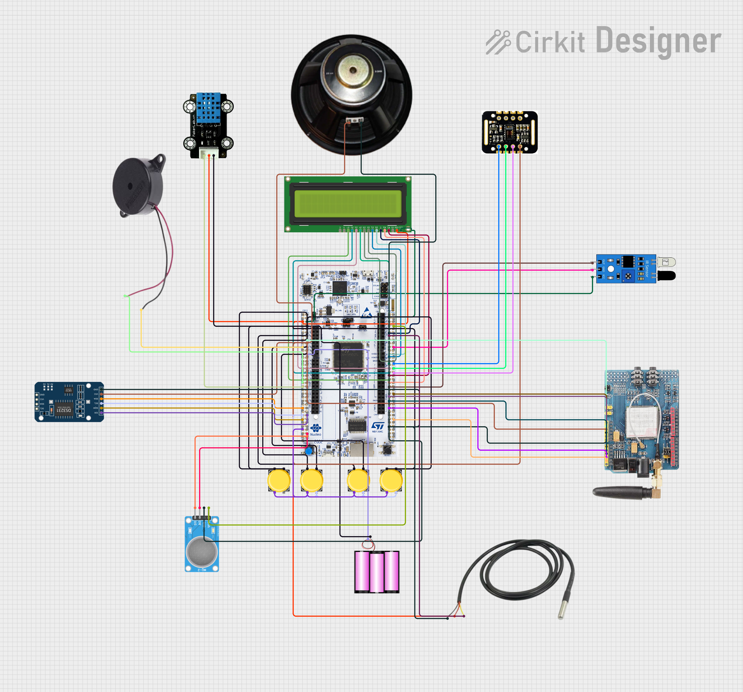


Explore Projects Built with HC12 (1)
Common Applications and Use Cases
- Wireless sensor networks
- Remote control systems
- Home automation
- Industrial monitoring and control
- Internet of Things (IoT) devices
- Data logging and telemetry
Technical Specifications
The HC12 microcontroller is equipped with features that make it suitable for wireless communication in embedded systems. Below are its key technical specifications:
| Parameter | Value |
|---|---|
| Operating Voltage | 3.2V to 5.5V |
| Operating Current | 16 mA (transmitting), 3.5 mA (receiving) |
| Sleep Current | < 22 µA |
| RF Frequency Range | 433.4 MHz to 473.0 MHz |
| Communication Range | Up to 1,000 meters (line of sight) |
| Modulation Method | GFSK (Gaussian Frequency Shift Keying) |
| Baud Rate (Serial) | 1,200 bps to 115,200 bps |
| RF Data Rate | 500 bps to 19,200 bps |
| Output Power | -1 dBm to 20 dBm (adjustable) |
| Operating Temperature | -40°C to +85°C |
| Dimensions | 27.8 mm x 14.4 mm x 4 mm |
Pin Configuration and Descriptions
The HC12 module has a total of 4 main pins for interfacing. Below is the pinout and description:
| Pin | Name | Description |
|---|---|---|
| 1 | VCC | Power supply input (3.2V to 5.5V). |
| 2 | GND | Ground connection. |
| 3 | TXD | Serial data output (connects to RXD of the microcontroller). |
| 4 | RXD | Serial data input (connects to TXD of the microcontroller). |
| 5 | SET | Mode selection pin (used to configure the module or enter sleep mode). |
Usage Instructions
The HC12 module is straightforward to use in a circuit. Below are the steps and best practices for integrating it into your project:
Basic Circuit Connection
- Power Supply: Connect the VCC pin to a 3.3V or 5V power source and the GND pin to ground.
- Serial Communication: Connect the TXD pin of the HC12 to the RXD pin of your microcontroller (e.g., Arduino UNO) and the RXD pin of the HC12 to the TXD pin of the microcontroller.
- Mode Selection: Leave the SET pin unconnected for normal operation. Pull it low (connect to GND) to enter configuration mode.
Configuring the HC12
To configure the HC12 module (e.g., change baud rate, RF power, or channel), follow these steps:
Pull the SET pin low to enter configuration mode.
Send AT commands via the serial interface to configure the module. For example:
AT+B9600sets the baud rate to 9600 bps.AT+P8sets the RF power to 8 (maximum).AT+C001sets the communication channel to 1.
Pull the SET pin high (or leave it unconnected) to exit configuration mode and resume normal operation.
Example: Using HC12 with Arduino UNO
Below is an example of how to use the HC12 module with an Arduino UNO for basic communication:
Circuit Diagram
- Connect HC12's VCC to Arduino's 5V.
- Connect HC12's GND to Arduino's GND.
- Connect HC12's TXD to Arduino's D2 (via a voltage divider if using 5V logic).
- Connect HC12's RXD to Arduino's D3.
Arduino Code
#include <SoftwareSerial.h>

// Define RX and TX pins for SoftwareSerial
SoftwareSerial HC12(2, 3); // RX = Pin 2, TX = Pin 3

void setup() {
  Serial.begin(9600);       // Start the hardware serial port
  HC12.begin(9600);         // Start the HC12 serial communication
  Serial.println("HC12 Ready");
}

void loop() {
  // Check if data is received from the HC12
  if (HC12.available()) {
    String receivedData = HC12.readString(); // Read data from HC12
    Serial.print("Received: ");
    Serial.println(receivedData);           // Print received data to Serial Monitor
  }

  // Check if data is sent from the Serial Monitor
  if (Serial.available()) {
    String sendData = Serial.readString();  // Read data from Serial Monitor
    HC12.print(sendData);                   // Send data to HC12
  }
}
Important Considerations
- Use a voltage divider or level shifter if your microcontroller operates at 5V logic levels, as the HC12 operates at 3.3V logic.
- Avoid placing the HC12 module near high-frequency components or metal objects to minimize interference.
- Ensure the antenna is securely connected for optimal range and performance.
Troubleshooting and FAQs
Common Issues and Solutions
No Communication Between Modules
- Ensure both modules are configured to the same baud rate, channel, and RF data rate.
- Verify the wiring connections, especially TXD and RXD.
Short Communication Range
- Check the antenna connection and ensure it is properly installed.
- Increase the RF power using the
AT+Pcommand.
Module Not Responding to AT Commands
- Ensure the SET pin is pulled low to enter configuration mode.
- Verify the baud rate of the serial interface matches the module's default (9600 bps).
High Power Consumption
- Use the sleep mode to reduce power consumption when the module is idle. Pull the SET pin low and send the
AT+SLEEPcommand.
- Use the sleep mode to reduce power consumption when the module is idle. Pull the SET pin low and send the
FAQs
Q: Can the HC12 communicate with other RF modules?
A: No, the HC12 can only communicate with other HC12 modules configured to the same settings.
Q: What is the maximum range of the HC12?
A: The HC12 can achieve up to 1,000 meters in line-of-sight conditions with a proper antenna.
Q: How do I reset the HC12 to factory settings?
A: Enter configuration mode (SET pin low) and send the AT+DEFAULT command.
Q: Can I use the HC12 with a 5V microcontroller?
A: Yes, but you must use a voltage divider or level shifter for the RXD pin to avoid damaging the module.
By following this documentation, you can effectively integrate and troubleshoot the HC12 module in your wireless communication projects.