How to Use RS485 to TTL Converter : Examples, Pinouts, and Specs
Introduction
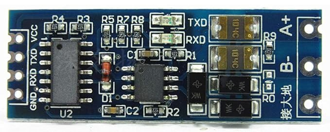
The RS485 to TTL Converter, manufactured by Arduino (Part ID: RS485 to TTL), is a device designed to convert RS485 signals to TTL (Transistor-Transistor Logic) levels. This conversion allows seamless communication between devices that operate at different voltage levels, making it an essential component in various electronic projects and industrial applications.
Explore Projects Built with RS485 to TTL Converter


Explore Projects Built with RS485 to TTL Converter
Common Applications and Use Cases
- Industrial Automation: Facilitates communication between PLCs and sensors.
- Home Automation: Connects various smart devices and controllers.
- Robotics: Enables communication between microcontrollers and motor drivers.
- Data Acquisition Systems: Interfaces sensors with data loggers.
- Serial Communication: Converts RS485 signals for use with TTL-compatible devices like Arduino.
Technical Specifications
Key Technical Details
| Parameter | Value |
|---|---|
| Operating Voltage | 3.3V to 5V |
| Communication Protocol | RS485 to TTL |
| Baud Rate | Up to 115200 bps |
| Operating Temperature | -40°C to 85°C |
| Dimensions | 25mm x 15mm x 5mm |
Pin Configuration and Descriptions
| Pin Number | Pin Name | Description |
|---|---|---|
| 1 | VCC | Power supply (3.3V to 5V) |
| 2 | GND | Ground |
| 3 | RO | Receiver Output (TTL level) |
| 4 | RE | Receiver Enable (Active Low) |
| 5 | DE | Driver Enable (Active High) |
| 6 | DI | Driver Input (TTL level) |
| 7 | A | RS485 A (Non-inverting) |
| 8 | B | RS485 B (Inverting) |
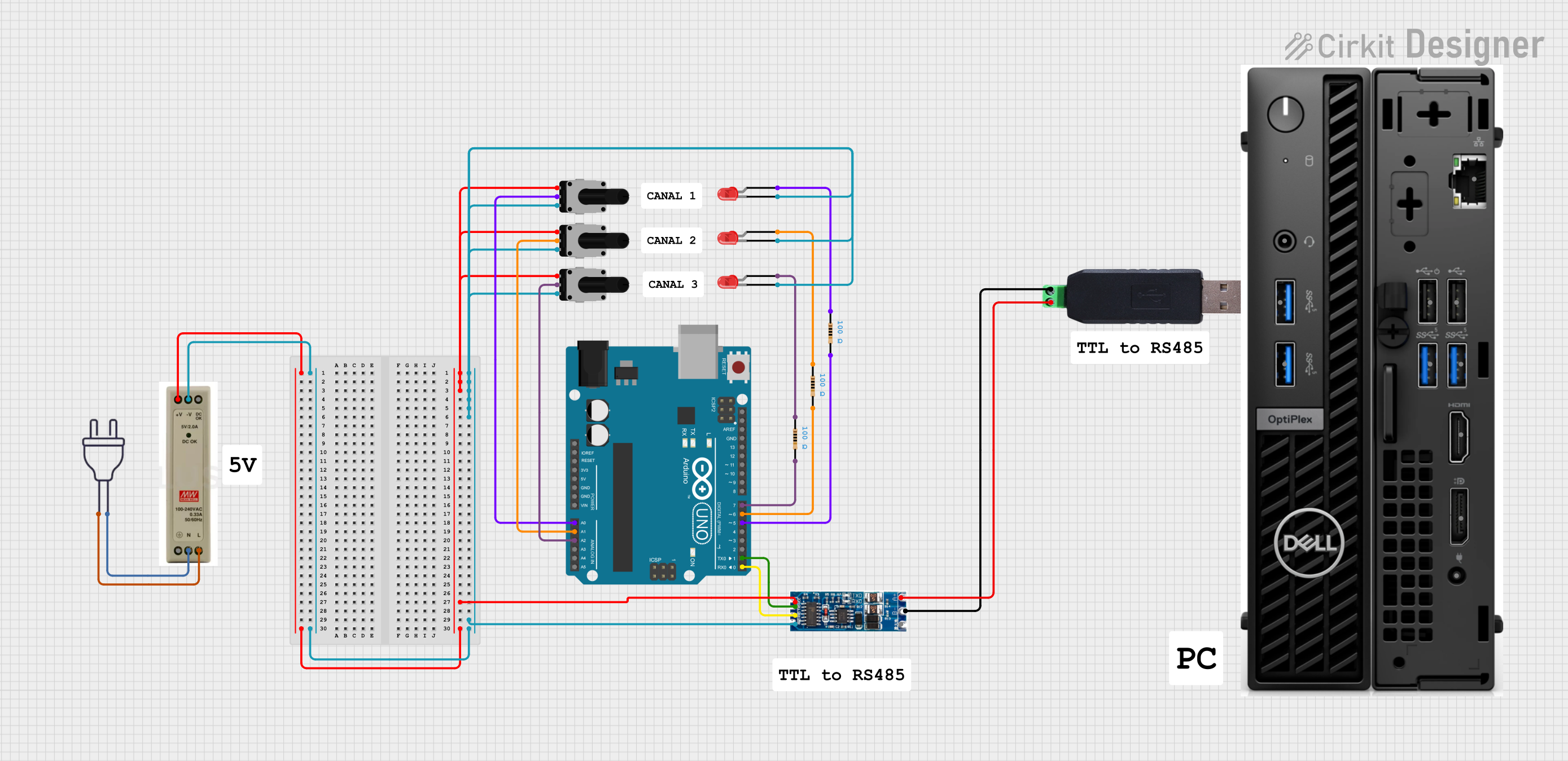
Usage Instructions
How to Use the Component in a Circuit
Power Supply:
- Connect the VCC pin to a 3.3V or 5V power supply.
- Connect the GND pin to the ground of your circuit.
RS485 Connection:
- Connect the A pin to the non-inverting RS485 line.
- Connect the B pin to the inverting RS485 line.
TTL Connection:
- Connect the RO pin to the RX pin of your microcontroller (e.g., Arduino).
- Connect the DI pin to the TX pin of your microcontroller.
Control Pins:
- Connect the RE pin to ground to enable the receiver.
- Connect the DE pin to VCC to enable the driver.
Important Considerations and Best Practices
- Termination Resistor: Use a 120-ohm termination resistor between A and B lines for long-distance communication.
- Noise Reduction: Keep RS485 lines twisted and shielded to minimize noise.
- Baud Rate Matching: Ensure the baud rate of the RS485 device matches the baud rate of the TTL device.
- Proper Grounding: Ensure all devices share a common ground to avoid communication issues.
Example Code for Arduino UNO
// Example code to communicate with RS485 to TTL Converter using Arduino UNO

#include <SoftwareSerial.h>

// Define the pins for RS485 to TTL Converter
#define RX_PIN 10  // Receiver pin
#define TX_PIN 11  // Transmitter pin

// Create a SoftwareSerial object
SoftwareSerial rs485Serial(RX_PIN, TX_PIN);

void setup() {
  // Start the serial communication with the RS485 device
  rs485Serial.begin(9600);
  // Start the serial communication with the Serial Monitor
  Serial.begin(9600);
}

void loop() {
  // Check if data is available from the RS485 device
  if (rs485Serial.available()) {
    // Read the data from the RS485 device
    char data = rs485Serial.read();
    // Print the data to the Serial Monitor
    Serial.print("Received: ");
    Serial.println(data);
  }

  // Check if data is available from the Serial Monitor
  if (Serial.available()) {
    // Read the data from the Serial Monitor
    char data = Serial.read();
    // Send the data to the RS485 device
    rs485Serial.write(data);
  }
}
Troubleshooting and FAQs
Common Issues Users Might Face
No Communication:
- Solution: Check all connections, ensure proper grounding, and verify baud rates.
Data Corruption:
- Solution: Use a termination resistor and ensure RS485 lines are twisted and shielded.
Intermittent Communication:
- Solution: Check for loose connections and ensure all devices share a common ground.
FAQs
Q1: Can I use the RS485 to TTL Converter with a 3.3V microcontroller?
- A1: Yes, the converter supports both 3.3V and 5V logic levels.
Q2: What is the maximum communication distance for RS485?
- A2: RS485 can communicate up to 1200 meters (4000 feet) under ideal conditions.
Q3: Do I need to use both RE and DE pins?
- A3: Yes, RE and DE pins control the receiver and driver modes, respectively. Connect RE to ground and DE to VCC for normal operation.
Q4: Can I connect multiple RS485 devices to a single TTL device?
- A4: Yes, RS485 supports multi-drop communication, allowing multiple devices on the same bus.
By following this documentation, users can effectively integrate the RS485 to TTL Converter into their projects, ensuring reliable and efficient communication between devices with different voltage levels.