How to Use IR LED matrix 8x6: Examples, Pinouts, and Specs
Introduction
The IR LED Matrix 8x6 is a compact and efficient array of 48 infrared LEDs arranged in 8 rows and 6 columns. This component is designed to emit infrared light, which is invisible to the human eye but can be detected by IR receivers, sensors, and cameras. It is commonly used in applications such as remote control systems, proximity sensing, object detection, and infrared communication.
The matrix design allows for precise control of individual LEDs or groups of LEDs, making it suitable for dynamic and programmable IR light patterns. Its compact form factor and versatility make it a popular choice for hobbyists, engineers, and researchers.
Explore Projects Built with IR LED matrix 8x6

Explore Projects Built with IR LED matrix 8x6
Technical Specifications
- Number of LEDs: 48 (8 rows × 6 columns)
- LED Type: Infrared (IR)
- Wavelength: 850 nm to 950 nm (typical: 940 nm)
- Forward Voltage (per LED): 1.2V to 1.5V
- Forward Current (per LED): 20 mA (typical), 30 mA (maximum)
- Matrix Configuration: Common cathode or common anode (varies by model)
- Operating Temperature: -25°C to 85°C
- Dimensions: Varies by manufacturer (e.g., 50mm × 40mm)
Pin Configuration and Descriptions
The IR LED Matrix 8x6 has multiple pins for controlling the rows and columns. Below is a typical pin configuration:
| Pin Name | Description |
|---|---|
| R1 to R8 | Row control pins (R1 = Row 1, R8 = Row 8) |
| C1 to C6 | Column control pins (C1 = Column 1, C6 = Column 6) |
| GND | Ground connection (common cathode models) |
| VCC | Power supply (common anode models) |
Note: The exact pinout may vary depending on the manufacturer. Always refer to the datasheet for your specific model.
Usage Instructions
How to Use the IR LED Matrix in a Circuit
- Power Supply: Ensure the matrix is powered with the correct voltage and current. Use current-limiting resistors (typically 220Ω to 330Ω) in series with each LED to prevent overcurrent.
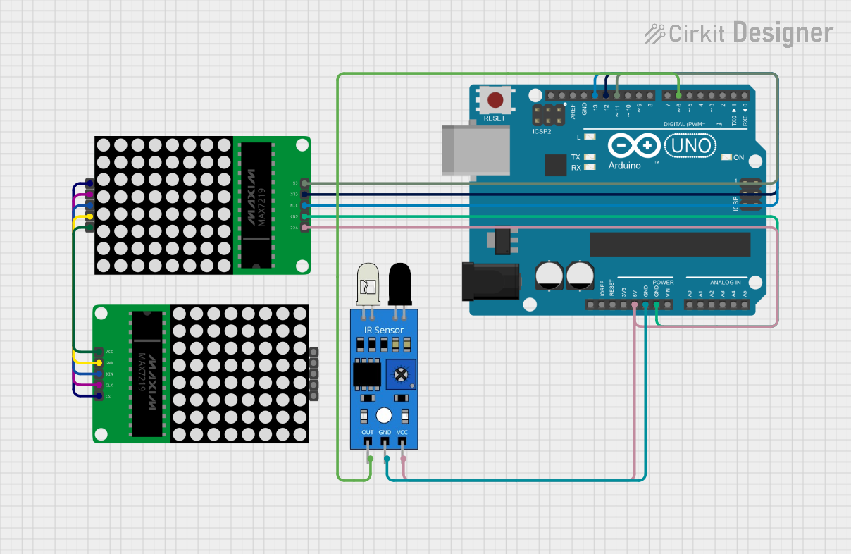
- Control Method: Use a microcontroller (e.g., Arduino UNO) or a driver IC to control the rows and columns. Multiplexing is commonly used to control individual LEDs.
- Wiring:
- For a common cathode matrix, connect the cathode pins (rows) to ground and control the anode pins (columns) with a positive voltage.
- For a common anode matrix, connect the anode pins (rows) to VCC and control the cathode pins (columns) with ground.
Example: Connecting to an Arduino UNO
Below is an example of how to control the IR LED Matrix 8x6 using an Arduino UNO. This example lights up a single LED at the intersection of Row 2 and Column 3.
// Define row and column pins
const int rowPins[8] = {2, 3, 4, 5, 6, 7, 8, 9}; // Arduino pins for rows
const int colPins[6] = {10, 11, 12, A0, A1, A2}; // Arduino pins for columns

void setup() {
  // Set all row pins as OUTPUT and initialize them to HIGH
  for (int i = 0; i < 8; i++) {
    pinMode(rowPins[i], OUTPUT);
    digitalWrite(rowPins[i], HIGH);
  }

  // Set all column pins as OUTPUT and initialize them to LOW
  for (int i = 0; i < 6; i++) {
    pinMode(colPins[i], OUTPUT);
    digitalWrite(colPins[i], LOW);
  }
}

void loop() {
  // Light up the LED at Row 2 (R2) and Column 3 (C3)
  digitalWrite(rowPins[1], LOW);  // Activate Row 2 (set LOW for common cathode)
  digitalWrite(colPins[2], HIGH); // Activate Column 3 (set HIGH for common cathode)

  delay(1000); // Keep the LED on for 1 second

  // Turn off the LED
  digitalWrite(rowPins[1], HIGH); // Deactivate Row 2
  digitalWrite(colPins[2], LOW);  // Deactivate Column 3

  delay(1000); // Wait for 1 second before repeating
}
Important Considerations:
- Use appropriate resistors to limit current through the LEDs.
- Avoid driving multiple LEDs simultaneously without proper current management.
- If using PWM (Pulse Width Modulation) for brightness control, ensure the frequency is high enough to avoid flickering.
Troubleshooting and FAQs
Common Issues and Solutions
No LEDs are lighting up:
- Check the power supply and ensure the matrix is receiving the correct voltage and current.
- Verify the wiring and connections to the microcontroller or driver IC.
- Ensure the correct pins are being activated in the code.
LEDs are dim:
- Check the value of the current-limiting resistors. Lower the resistance slightly if safe to do so.
- Ensure the power supply can provide sufficient current for the number of LEDs being driven.
Multiple LEDs light up unintentionally:
- Verify the multiplexing logic in your code. Ensure only one row and one column are active at a time.
- Check for short circuits or unintended connections between rows and columns.
Flickering LEDs:
- Increase the refresh rate of the multiplexing to reduce visible flicker.
- Ensure the microcontroller is not overloaded with other tasks.
FAQs
Q: Can I use the IR LED Matrix for data transmission?
A: Yes, the matrix can be used for infrared communication by modulating the LEDs at a specific frequency (e.g., 38 kHz). This requires additional circuitry or software to generate the modulation.
Q: How do I detect the IR light emitted by the matrix?
A: Use an IR receiver module or an IR-sensitive photodiode to detect the emitted light. Ensure the receiver is tuned to the wavelength of the LEDs (typically 940 nm).
Q: Can I power the matrix directly from the Arduino?
A: It is not recommended to power the entire matrix directly from the Arduino, as the current requirements may exceed the Arduino's limits. Use an external power supply and appropriate driver circuitry.
Q: Is the matrix visible to standard cameras?
A: Most standard cameras can detect IR light, but the intensity may vary. Use an IR-sensitive camera for better visibility.