How to Use Color Sensor: Examples, Pinouts, and Specs
Introduction
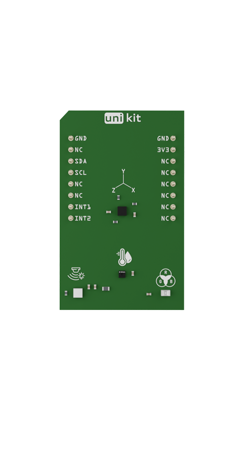
The Mikroe Color Sensor is a device designed to detect and measure the color of an object or surface. It provides precise color data by analyzing the intensity of red, green, and blue light reflected from the target. This sensor is widely used in robotics, automation, and industrial applications where color recognition is essential for decision-making processes. Its compact design and reliable performance make it an excellent choice for projects requiring accurate color detection.
Explore Projects Built with Color Sensor

Explore Projects Built with Color Sensor
Common Applications
- Robotics: Line-following robots or object sorting based on color.
- Industrial Automation: Quality control and product sorting.
- Consumer Electronics: Color-based user interfaces or smart home devices.
- Education: STEM projects and learning about color detection principles.
Technical Specifications
The Mikroe Color Sensor is built for versatility and ease of integration into various systems. Below are its key technical details:
Key Specifications
- Operating Voltage: 3.3V or 5V (depending on the configuration)
- Current Consumption: ~10mA (typical)
- Communication Interface: I2C
- Spectral Range: 400nm to 700nm (visible light spectrum)
- Output Data: Red, Green, Blue (RGB) intensity values
- Operating Temperature: -40°C to 85°C
- Dimensions: 25mm x 25mm x 5mm
Pin Configuration and Descriptions
The Mikroe Color Sensor typically comes with a 6-pin interface. Below is the pinout description:
| Pin | Name | Description |
|---|---|---|
| 1 | VCC | Power supply input (3.3V or 5V) |
| 2 | GND | Ground |
| 3 | SDA | I2C data line |
| 4 | SCL | I2C clock line |
| 5 | INT | Interrupt pin (optional, for alerts) |
| 6 | LED | LED control pin (optional, for illumination) |
Usage Instructions
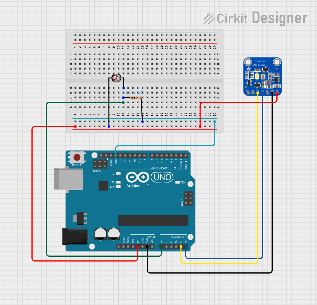
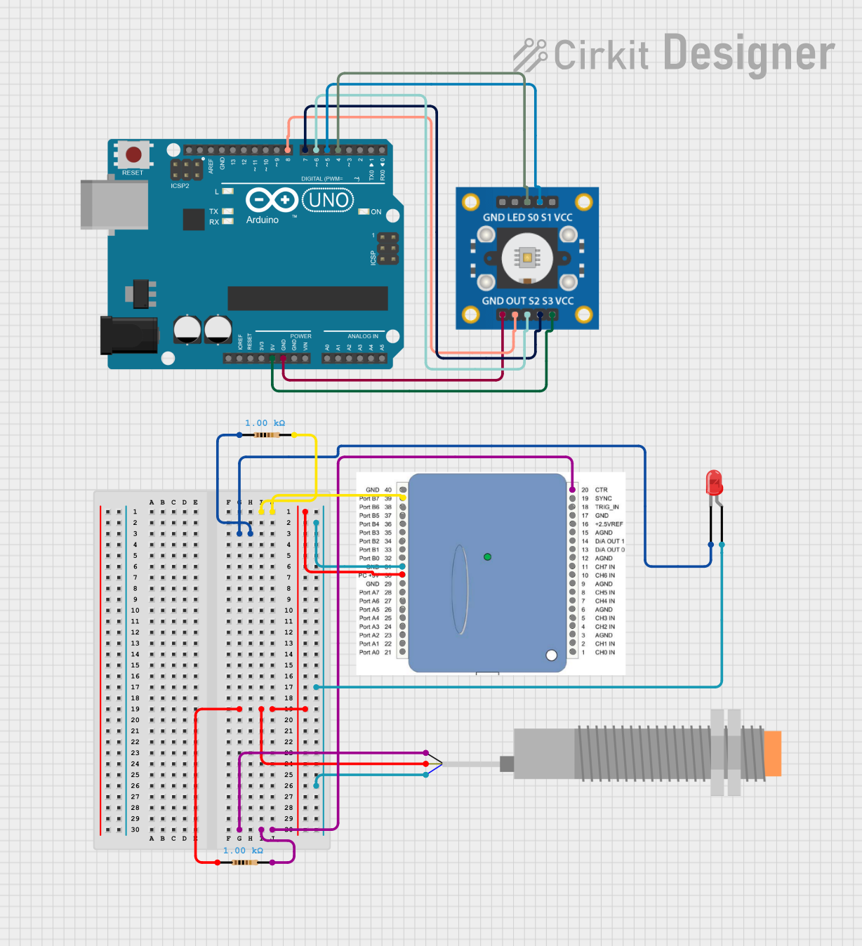
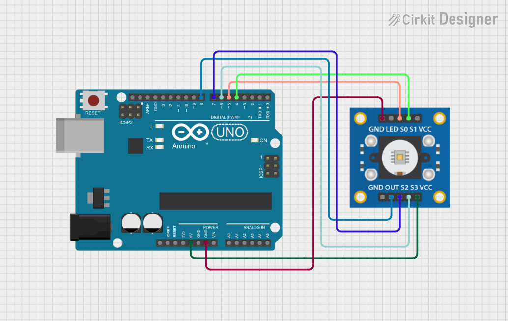
How to Use the Color Sensor in a Circuit
- Power the Sensor: Connect the VCC pin to a 3.3V or 5V power source and the GND pin to ground.
- Connect I2C Lines: Attach the SDA and SCL pins to the corresponding I2C pins on your microcontroller (e.g., Arduino UNO).
- Optional Connections:
- Use the INT pin if you need interrupt-based alerts.
- Connect the LED pin to control the onboard illumination LED.
- Pull-Up Resistors: Ensure that the I2C lines (SDA and SCL) have appropriate pull-up resistors (typically 4.7kΩ).
Best Practices
- Calibration: Calibrate the sensor for accurate color detection under specific lighting conditions.
- Ambient Light: Minimize ambient light interference by using the onboard LED or enclosing the sensor.
- I2C Address: Check the default I2C address in the datasheet and ensure it does not conflict with other devices on the bus.
Example Code for Arduino UNO
Below is an example of how to interface the Mikroe Color Sensor with an Arduino UNO to read RGB values:
#include <Wire.h>

// Define the I2C address of the color sensor
#define COLOR_SENSOR_ADDR 0x29

void setup() {
  Wire.begin(); // Initialize I2C communication
  Serial.begin(9600); // Start serial communication for debugging

  // Initialize the color sensor
  Wire.beginTransmission(COLOR_SENSOR_ADDR);
  // Example: Write initialization commands to the sensor
  Wire.write(0x00); // Replace with actual register address
  Wire.write(0x01); // Replace with actual initialization value
  Wire.endTransmission();

  Serial.println("Color Sensor Initialized");
}

void loop() {
  // Request RGB data from the sensor
  Wire.beginTransmission(COLOR_SENSOR_ADDR);
  Wire.write(0x03); // Replace with the register address for RGB data
  Wire.endTransmission();

  Wire.requestFrom(COLOR_SENSOR_ADDR, 3); // Request 3 bytes (R, G, B)
  if (Wire.available() == 3) {
    int red = Wire.read();   // Read red intensity
    int green = Wire.read(); // Read green intensity
    int blue = Wire.read();  // Read blue intensity

    // Print the RGB values to the serial monitor
    Serial.print("R: ");
    Serial.print(red);
    Serial.print(" G: ");
    Serial.print(green);
    Serial.print(" B: ");
    Serial.println(blue);
  }

  delay(500); // Wait for 500ms before the next reading
}
Notes
- Replace the register addresses and initialization values in the code with those specified in the Mikroe Color Sensor datasheet.
- Ensure the I2C address matches the sensor's default or configured address.
Troubleshooting and FAQs
Common Issues
- No Data from the Sensor:
- Check the I2C connections (SDA, SCL) and ensure pull-up resistors are in place.
- Verify the sensor's I2C address and update the code if necessary.
- Inaccurate Color Readings:
- Calibrate the sensor under the actual lighting conditions of your application.
- Ensure the sensor is not exposed to excessive ambient light.
- Sensor Not Detected:
- Confirm the power supply voltage is within the specified range.
- Use an I2C scanner sketch to detect the sensor's address.
Tips for Troubleshooting
- Use a multimeter to verify power and ground connections.
- Test the I2C bus with an I2C scanner to ensure communication is working.
- Refer to the Mikroe Color Sensor datasheet for detailed register descriptions and configuration options.
By following this documentation, you can effectively integrate the Mikroe Color Sensor into your projects and achieve reliable color detection.