Cirkit Designer Logo
Cirkit Designer
Your all-in-one circuit design IDE
Home / 
Component Documentation

How to Use Esp32: Examples, Pinouts, and Specs

Image of Esp32
Cirkit Designer LogoDesign with Esp32 in Cirkit Designer

Introduction

The ESP32 is a low-cost, low-power system on a chip (SoC) developed by Espressif Systems. It features integrated Wi-Fi and Bluetooth capabilities, making it an ideal choice for Internet of Things (IoT) applications, smart devices, and embedded systems. The ESP32 is highly versatile, offering dual-core processing, a wide range of GPIO pins, and support for various communication protocols.

Explore Projects Built with Esp32

Use Cirkit Designer to design, explore, and prototype these projects online. Some projects support real-time simulation. Click "Open Project" to start designing instantly!
ESP32-Based Sensor Monitoring System with OLED Display and E-Stop
Image of MVP_design: A project utilizing Esp32 in a practical application
This circuit features an ESP32 microcontroller that interfaces with a variety of sensors and output devices. It is powered by a Lipo battery through a buck converter, ensuring a stable voltage supply. The ESP32 collects data from a DHT11 temperature and humidity sensor and a vibration sensor, controls a buzzer, and displays information on an OLED screen. An emergency stop (E Stop) is connected for safety purposes, allowing the system to be quickly deactivated.
Cirkit Designer LogoOpen Project in Cirkit Designer
ESP32-Controlled OLED Display and Servo with DotStar LED Strip and Audio Output
Image of Arena 2: A project utilizing Esp32 in a practical application
This circuit features an ESP32 microcontroller driving a variety of components. It controls an OLED display for visual output, a DotStar LED strip for lighting effects, a PAM8403 audio amplifier connected to a speaker for sound output, and a PCA9685 PWM Servo Breakout to manage a servo motor. The ESP32 also interfaces with a piezo speaker for additional sound generation, and the circuit is powered by a 18650 Li-ion battery setup with a TP4056 charging module. The ESP32's embedded code handles the display animation on the OLED.
Cirkit Designer LogoOpen Project in Cirkit Designer
ESP32-Based Environmental Monitoring System with Motion Detection
Image of pro: A project utilizing Esp32 in a practical application
This circuit features an ESP32 microcontroller on a baseboard that interfaces with a PIR sensor for motion detection, a DHT22 sensor for measuring temperature and humidity, and a BH1750 sensor for detecting ambient light levels. The ESP32 is configured to communicate with the BH1750 using I2C protocol, with GPIO22 and GPIO21 serving as the SCL and SDA lines, respectively. Power is supplied to the sensors from the ESP32's voltage output pins, and sensor outputs are connected to designated GPIO pins for data acquisition.
Cirkit Designer LogoOpen Project in Cirkit Designer
ESP32-Based Infrared Thermometer with I2C LCD Display
Image of infrared thermometer: A project utilizing Esp32 in a practical application
This circuit features an ESP32 microcontroller powered by a 18650 Li-Ion battery, with a TP4056 module for charging the battery via a USB plug. The ESP32 reads temperature data from an MLX90614 infrared temperature sensor and displays it on an I2C LCD 16x2 screen. The ESP32, MLX90614 sensor, and LCD screen are connected via I2C communication lines (SCL, SDA), and the circuit is designed to measure and display ambient and object temperatures.
Cirkit Designer LogoOpen Project in Cirkit Designer

Explore Projects Built with Esp32

Use Cirkit Designer to design, explore, and prototype these projects online. Some projects support real-time simulation. Click "Open Project" to start designing instantly!
Image of MVP_design: A project utilizing Esp32 in a practical application
ESP32-Based Sensor Monitoring System with OLED Display and E-Stop
This circuit features an ESP32 microcontroller that interfaces with a variety of sensors and output devices. It is powered by a Lipo battery through a buck converter, ensuring a stable voltage supply. The ESP32 collects data from a DHT11 temperature and humidity sensor and a vibration sensor, controls a buzzer, and displays information on an OLED screen. An emergency stop (E Stop) is connected for safety purposes, allowing the system to be quickly deactivated.
Cirkit Designer LogoOpen Project in Cirkit Designer
Image of Arena 2: A project utilizing Esp32 in a practical application
ESP32-Controlled OLED Display and Servo with DotStar LED Strip and Audio Output
This circuit features an ESP32 microcontroller driving a variety of components. It controls an OLED display for visual output, a DotStar LED strip for lighting effects, a PAM8403 audio amplifier connected to a speaker for sound output, and a PCA9685 PWM Servo Breakout to manage a servo motor. The ESP32 also interfaces with a piezo speaker for additional sound generation, and the circuit is powered by a 18650 Li-ion battery setup with a TP4056 charging module. The ESP32's embedded code handles the display animation on the OLED.
Cirkit Designer LogoOpen Project in Cirkit Designer
Image of pro: A project utilizing Esp32 in a practical application
ESP32-Based Environmental Monitoring System with Motion Detection
This circuit features an ESP32 microcontroller on a baseboard that interfaces with a PIR sensor for motion detection, a DHT22 sensor for measuring temperature and humidity, and a BH1750 sensor for detecting ambient light levels. The ESP32 is configured to communicate with the BH1750 using I2C protocol, with GPIO22 and GPIO21 serving as the SCL and SDA lines, respectively. Power is supplied to the sensors from the ESP32's voltage output pins, and sensor outputs are connected to designated GPIO pins for data acquisition.
Cirkit Designer LogoOpen Project in Cirkit Designer
Image of infrared thermometer: A project utilizing Esp32 in a practical application
ESP32-Based Infrared Thermometer with I2C LCD Display
This circuit features an ESP32 microcontroller powered by a 18650 Li-Ion battery, with a TP4056 module for charging the battery via a USB plug. The ESP32 reads temperature data from an MLX90614 infrared temperature sensor and displays it on an I2C LCD 16x2 screen. The ESP32, MLX90614 sensor, and LCD screen are connected via I2C communication lines (SCL, SDA), and the circuit is designed to measure and display ambient and object temperatures.
Cirkit Designer LogoOpen Project in Cirkit Designer

Common Applications and Use Cases

  • IoT devices (e.g., smart home automation, sensors, and actuators)
  • Wearable technology
  • Wireless communication systems
  • Robotics and drones
  • Data logging and monitoring systems
  • Prototyping and educational projects

Technical Specifications

The ESP32 is packed with features that make it a powerful and flexible component for a variety of applications. Below are its key technical specifications:

General Specifications

  • Processor: Dual-core Xtensa® 32-bit LX6 microprocessor
  • Clock Speed: Up to 240 MHz
  • RAM: 520 KB SRAM
  • Flash Memory: Typically 4 MB (varies by module)
  • Wi-Fi: 802.11 b/g/n (2.4 GHz)
  • Bluetooth: v4.2 BR/EDR and BLE
  • Operating Voltage: 3.3V
  • GPIO Pins: 34 (multipurpose, including ADC, DAC, PWM, I2C, SPI, UART)
  • Power Consumption: Ultra-low power consumption in deep sleep mode (~10 µA)

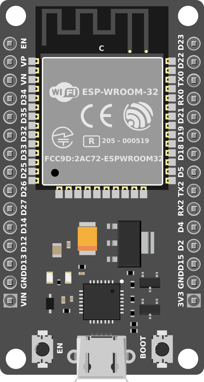
Pin Configuration and Descriptions

The ESP32 has multiple GPIO pins, each capable of serving different functions. Below is a table summarizing the key pins and their descriptions:

Pin Name Function Description
GPIO0 Input/Output, Boot Mode Selection Used for boot mode selection during startup.
GPIO2 Input/Output, ADC, DAC General-purpose pin, supports ADC and DAC.
GPIO12 Input/Output, ADC, Touch Sensor Can be used as an ADC input or touch sensor.
GPIO13 Input/Output, PWM, Touch Sensor Supports PWM and touch sensing.
GPIO15 Input/Output, ADC, PWM General-purpose pin with ADC and PWM support.
GPIO16 Input/Output General-purpose pin.
GPIO17 Input/Output General-purpose pin.
EN Enable Used to enable or reset the chip.
3V3 Power Provides 3.3V output.
GND Ground Ground connection.

Note: The ESP32 has many more GPIO pins and features. Refer to the official datasheet for a complete pinout.

Usage Instructions

The ESP32 is easy to integrate into a variety of projects. Below are the steps and best practices for using the ESP32 in a circuit.

Basic Setup

  1. Power Supply: Ensure the ESP32 is powered with a stable 3.3V source. Avoid exceeding this voltage to prevent damage.
  2. Connections:
    • Connect the GND pin to the ground of your circuit.
    • Use the 3V3 pin to power external components if needed.
  3. Programming:
    • The ESP32 can be programmed using the Arduino IDE or Espressif's ESP-IDF framework.
    • Connect the ESP32 to your computer via a USB-to-Serial adapter or a development board with built-in USB support.

Example: Blinking an LED with Arduino IDE

Below is an example of how to blink an LED connected to GPIO2 using the Arduino IDE:

// Define the GPIO pin where the LED is connected
#define LED_PIN 2

void setup() {
  // Set the LED pin as an output
  pinMode(LED_PIN, OUTPUT);
}

void loop() {
  // Turn the LED on
  digitalWrite(LED_PIN, HIGH);
  delay(1000); // Wait for 1 second

  // Turn the LED off
  digitalWrite(LED_PIN, LOW);
  delay(1000); // Wait for 1 second
}

Important Considerations

  • Voltage Levels: The ESP32 operates at 3.3V logic levels. Ensure any external components interfacing with the ESP32 are compatible with 3.3V.
  • Boot Mode: GPIO0 must be pulled low during startup to enter programming mode.
  • Power Consumption: Use deep sleep mode to minimize power usage in battery-powered applications.

Troubleshooting and FAQs

Common Issues

  1. ESP32 Not Detected by Computer:

    • Ensure the correct USB driver is installed for your development board.
    • Check the USB cable for faults or try a different cable.
  2. Upload Fails in Arduino IDE:

    • Verify the correct board and COM port are selected in the Arduino IDE.
    • Hold the BOOT button on the ESP32 board while uploading the code.
  3. Wi-Fi Connection Issues:

    • Double-check the SSID and password in your code.
    • Ensure the Wi-Fi network is within range and operational.
  4. Random Resets or Instability:

    • Check the power supply for stability. Use a capacitor to filter noise if necessary.
    • Avoid using GPIO pins that are reserved for specific functions during boot.

FAQs

Q: Can the ESP32 be powered with 5V?
A: No, the ESP32 operates at 3.3V. However, many development boards include a voltage regulator that allows them to be powered with 5V via USB.

Q: How do I reset the ESP32?
A: Press the EN (Enable) button on the development board to reset the ESP32.

Q: Can I use the ESP32 with sensors and modules designed for 5V?
A: Yes, but you will need a level shifter to safely interface 5V components with the ESP32's 3.3V logic.

Q: What is the maximum number of GPIO pins I can use?
A: The ESP32 has 34 GPIO pins, but some are reserved for specific functions. Refer to the datasheet for details.

By following this documentation, you can effectively use the ESP32 in your projects and troubleshoot common issues. For more advanced features, consult the official ESP32 datasheet and programming guides.