How to Use Quadrature Encoder AMT103: Examples, Pinouts, and Specs
Introduction
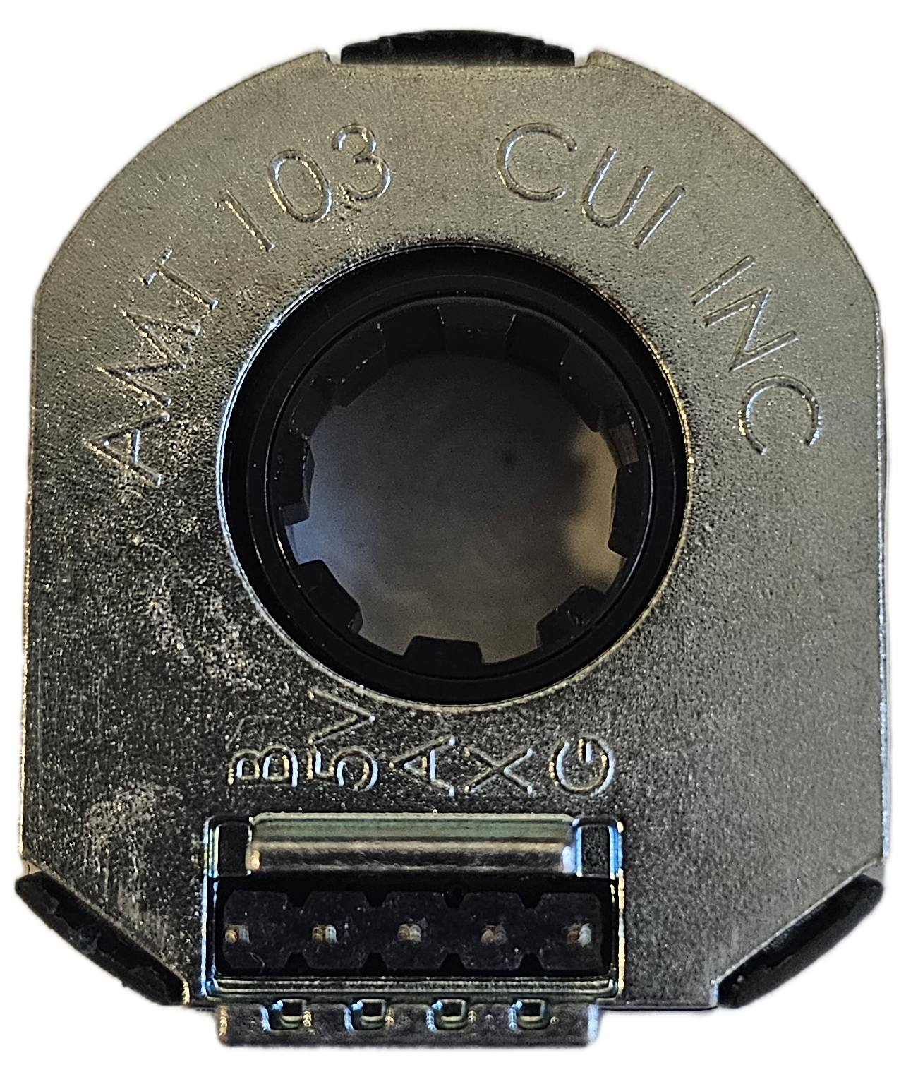
The AMT103 is a high-resolution quadrature encoder manufactured by Same Sky (formerly CUI Devices). It is designed to provide precise position and speed feedback for rotary applications. Utilizing optical sensing technology, the AMT103 detects the rotation of a shaft and outputs two square wave signals (A and B) that indicate both the direction and speed of rotation. This encoder is highly versatile and suitable for applications requiring accurate motion control.
Explore Projects Built with Quadrature Encoder AMT103


Explore Projects Built with Quadrature Encoder AMT103
Common Applications
- Robotics and automation systems
- CNC machines and 3D printers
- Motor control and feedback systems
- Industrial equipment requiring precise positioning
- Servo motor feedback
Technical Specifications
Key Technical Details
| Parameter | Value |
|---|---|
| Manufacturer Part ID | AMT103 |
| Resolution | Configurable: 48 to 2048 pulses per revolution (PPR) |
| Output Signal Type | Quadrature (A and B channels) |
| Supply Voltage | 4.5 V to 5.5 V |
| Current Consumption | 16 mA (typical) |
| Operating Temperature | -40°C to +100°C |
| Maximum Shaft Speed | 10,000 RPM |
| Output Voltage Levels | TTL-compatible |
| Mounting Options | Modular, with multiple shaft adapters |
Pin Configuration and Descriptions
The AMT103 has a 5-pin interface for power and signal output. The pinout is as follows:
| Pin Number | Name | Description |
|---|---|---|
| 1 | VCC | Power supply input (4.5 V to 5.5 V) |
| 2 | GND | Ground |
| 3 | A | Quadrature signal A (speed and direction) |
| 4 | B | Quadrature signal B (90° phase-shifted from A) |
| 5 | Index | Optional index pulse (1 pulse per revolution) |
Usage Instructions
How to Use the AMT103 in a Circuit
- Power Supply: Connect the VCC pin to a regulated 5V power source and the GND pin to the ground of your circuit.
- Signal Connections:
- Connect the A and B output pins to the input pins of a microcontroller or motor driver that supports quadrature decoding.
- Optionally, connect the Index pin if your application requires a reference pulse for each revolution.
- Mounting: Secure the encoder to the motor shaft using the provided mounting hardware and shaft adapters. Ensure proper alignment to avoid signal errors.
- Resolution Configuration: Use the included configuration tool or DIP switches (if applicable) to set the desired resolution (PPR).
Important Considerations and Best Practices
- Signal Decoding: Ensure your microcontroller or motor driver can interpret quadrature signals. Many microcontrollers, such as the Arduino UNO, have libraries or hardware support for quadrature decoding.
- Noise Filtering: Use pull-up resistors or capacitors to filter noise on the signal lines if necessary.
- Alignment: Properly align the encoder with the motor shaft to prevent wobbling or misalignment, which can cause inaccurate readings.
- Speed Limit: Do not exceed the maximum shaft speed of 10,000 RPM to avoid signal degradation.
Example: Connecting the AMT103 to an Arduino UNO
Below is an example of how to connect and read the AMT103 signals using an Arduino UNO:
// Example code to read quadrature encoder signals from the AMT103
// Connect A to pin 2, B to pin 3 on the Arduino UNO

volatile int encoderPosition = 0; // Variable to store encoder position
int lastEncoded = 0;              // Variable to store the last encoder state

void setup() {
  pinMode(2, INPUT_PULLUP); // Set pin 2 (A) as input with pull-up resistor
  pinMode(3, INPUT_PULLUP); // Set pin 3 (B) as input with pull-up resistor

  // Attach interrupts to handle encoder signals
  attachInterrupt(digitalPinToInterrupt(2), updateEncoder, CHANGE);
  attachInterrupt(digitalPinToInterrupt(3), updateEncoder, CHANGE);

  Serial.begin(9600); // Initialize serial communication
}

void loop() {
  // Print the current encoder position
  Serial.println(encoderPosition);
  delay(100); // Delay for readability
}

void updateEncoder() {
  // Read the current state of A and B
  int MSB = digitalRead(2); // Most significant bit (A)
  int LSB = digitalRead(3); // Least significant bit (B)

  int encoded = (MSB << 1) | LSB; // Combine A and B into a single value
  int sum = (lastEncoded << 2) | encoded; // Track state changes

  // Update position based on state transitions
  if (sum == 0b1101 || sum == 0b0100 || sum == 0b0010 || sum == 0b1011) {
    encoderPosition++;
  } else if (sum == 0b1110 || sum == 0b0111 || sum == 0b0001 || sum == 0b1000) {
    encoderPosition--;
  }

  lastEncoded = encoded; // Update the last state
}
Notes:
- Ensure the encoder is securely mounted to avoid signal errors.
- Use a stable 5V power supply to prevent voltage fluctuations.
Troubleshooting and FAQs
Common Issues and Solutions
No Signal Output:
- Verify the power supply voltage (4.5 V to 5.5 V).
- Check the connections to the A, B, and GND pins.
- Ensure the encoder is properly aligned with the motor shaft.
Inaccurate Position Readings:
- Check for misalignment or wobbling of the encoder.
- Ensure the resolution (PPR) is correctly configured for your application.
- Add pull-up resistors or capacitors to filter noise on the signal lines.
Signal Noise or Interference:
- Use shielded cables for signal lines.
- Keep the encoder wires away from high-power or noisy components.
Microcontroller Not Detecting Signals:
- Verify that the microcontroller pins are configured as inputs.
- Check the interrupt configuration if using an Arduino or similar platform.
FAQs
Q: Can the AMT103 be used with a 3.3V microcontroller?
A: Yes, the AMT103 outputs TTL-compatible signals, which are typically compatible with 3.3V logic. However, ensure the microcontroller can tolerate 5V signals or use a level shifter.
Q: How do I change the resolution (PPR)?
A: The AMT103 includes a configuration tool or DIP switches (depending on the model) to set the desired resolution. Refer to the manufacturer's manual for detailed instructions.
Q: What is the purpose of the Index pin?
A: The Index pin provides a single pulse per revolution, which can be used as a reference point for absolute positioning.
Q: Can the AMT103 handle high-speed applications?
A: Yes, the AMT103 supports shaft speeds up to 10,000 RPM, making it suitable for most high-speed applications.