How to Use QTRX 13A: Examples, Pinouts, and Specs
Introduction
The QTRX 13A, manufactured by Pololu (Part ID: HD 13A), is a high-performance relay designed for switching applications. It is capable of handling up to 13 amps of current, making it ideal for controlling high-power devices in electronic circuits. Its compact design ensures easy integration into various projects, including home automation, industrial control systems, and robotics.
Explore Projects Built with QTRX 13A


Explore Projects Built with QTRX 13A
Common Applications
- Home automation systems (e.g., controlling lights, fans, or appliances)
- Industrial equipment control
- Robotics and motor control
- Power management in electronic circuits
- Automotive electronics
Technical Specifications
The QTRX 13A relay is designed to provide reliable performance in demanding applications. Below are its key technical details:
General Specifications
| Parameter | Value |
|---|---|
| Manufacturer | Pololu |
| Part ID | HD 13A |
| Maximum Current Rating | 13 A |
| Operating Voltage | 5 V DC (coil voltage) |
| Contact Voltage Rating | Up to 250 V AC / 30 V DC |
| Contact Type | SPDT (Single Pole Double Throw) |
| Dimensions | 29 mm x 12.7 mm x 15 mm |
| Weight | 10 g |
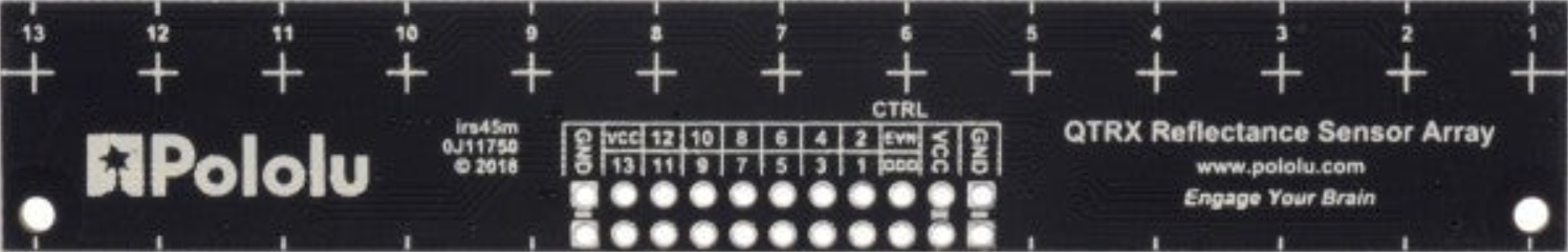
Pin Configuration
The QTRX 13A relay has five pins, as described in the table below:
| Pin Number | Pin Name | Description |
|---|---|---|
| 1 | Coil+ | Positive terminal of the relay coil (connect to 5 V DC) |
| 2 | Coil- | Negative terminal of the relay coil (connect to ground) |
| 3 | Common (COM) | Common terminal for the relay switch |
| 4 | Normally Open (NO) | Connected to COM when the relay is activated (switch closed) |
| 5 | Normally Closed (NC) | Connected to COM when the relay is deactivated (switch open) |
Usage Instructions
How to Use the QTRX 13A in a Circuit
- Power the Relay Coil: Connect the
Coil+pin to a 5 V DC power source and theCoil-pin to ground. This energizes the relay coil and switches the contacts. - Connect the Load:
- For devices that should turn on when the relay is activated, connect the load between the
COMandNOpins. - For devices that should turn off when the relay is activated, connect the load between the
COMandNCpins.
- For devices that should turn on when the relay is activated, connect the load between the
- Control the Relay: Use a microcontroller (e.g., Arduino UNO) or a transistor circuit to control the relay coil. Ensure the control circuit can handle the relay's coil current.
Important Considerations
- Flyback Diode: Always use a flyback diode across the relay coil to protect the control circuit from voltage spikes when the relay is deactivated.
- Current Rating: Ensure the load current does not exceed the relay's maximum rating of 13 A.
- Isolation: Use optocouplers or transistors to isolate the relay from sensitive control circuits if needed.
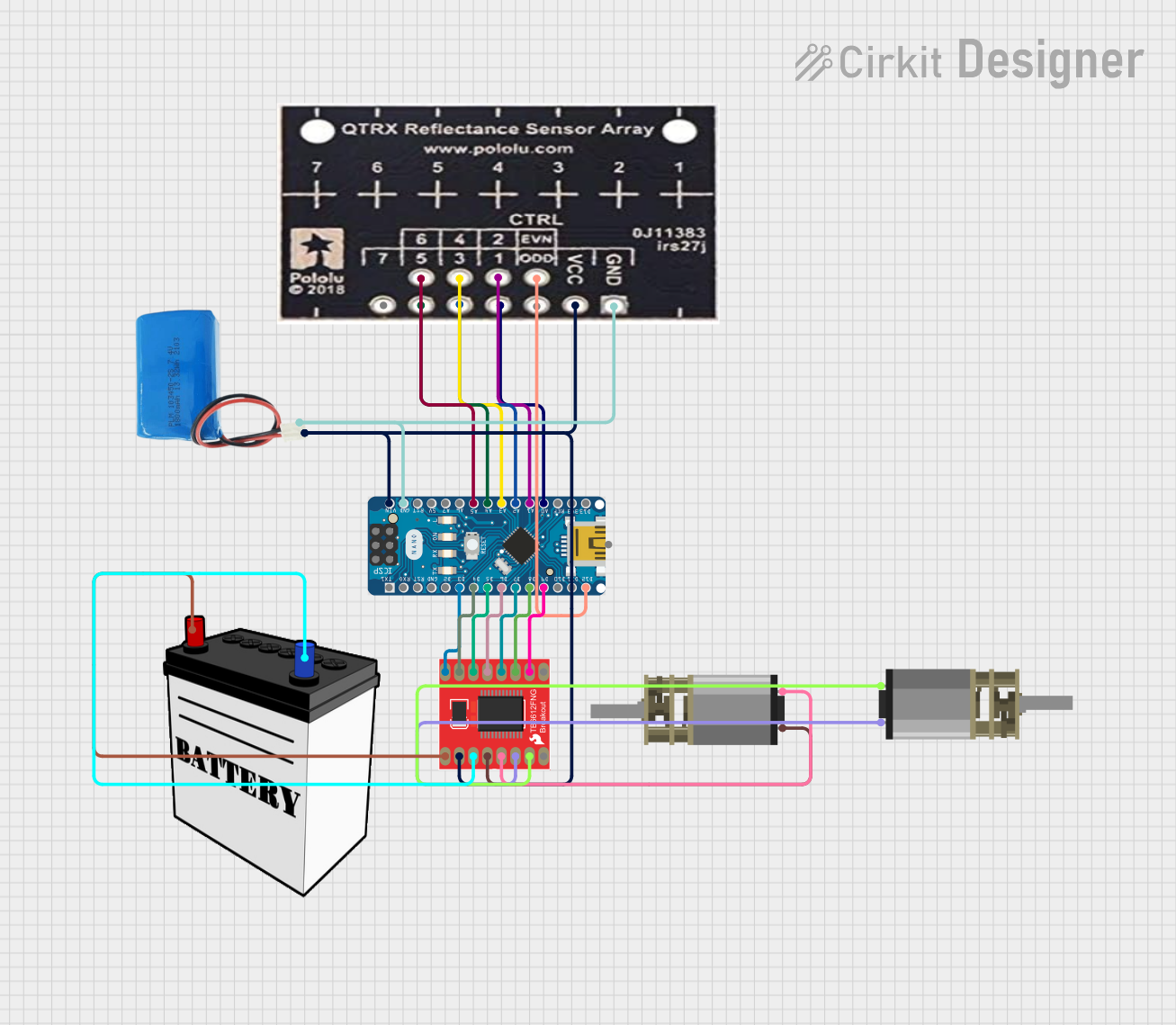
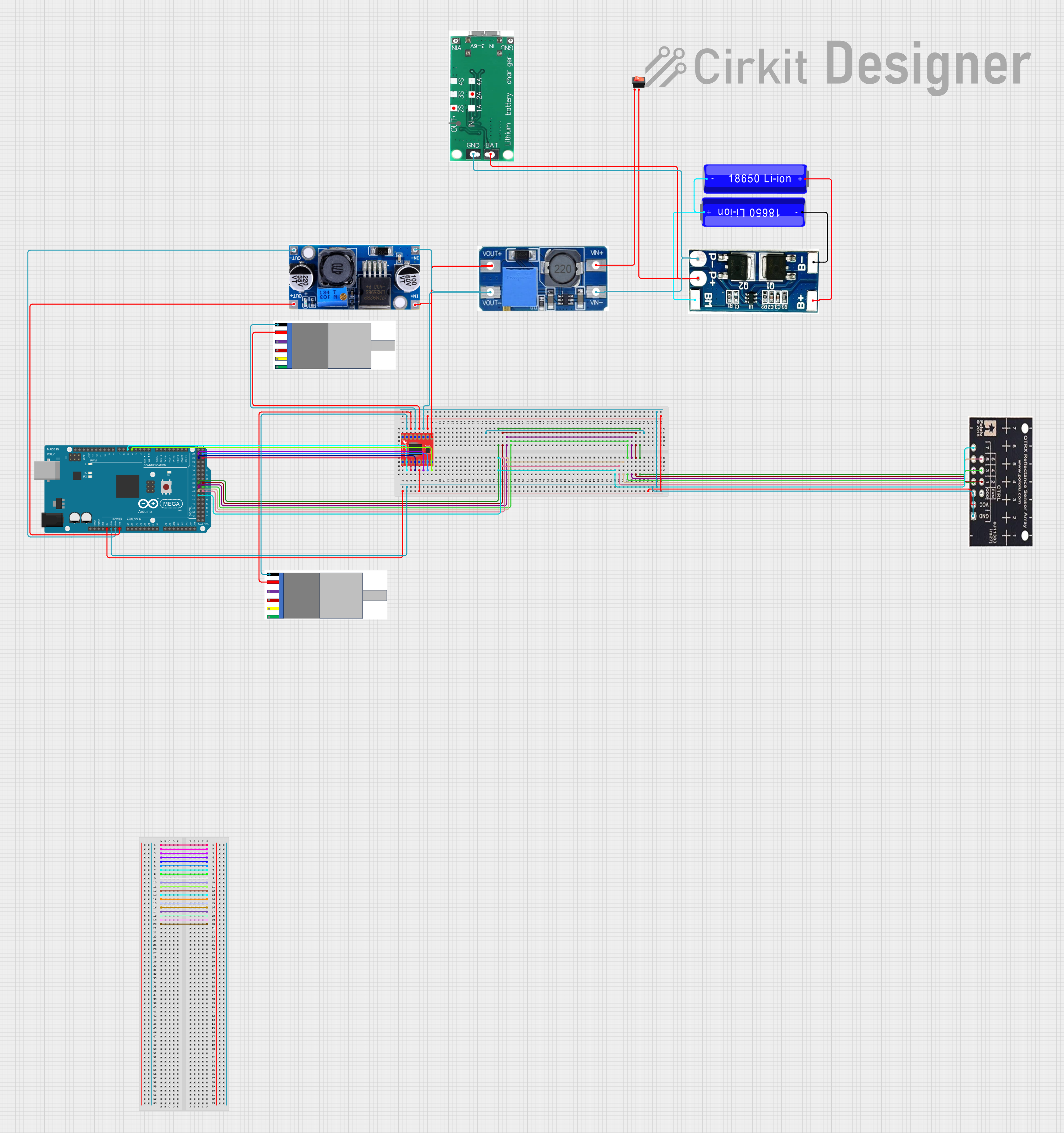
Example: Connecting QTRX 13A to an Arduino UNO
Below is an example of how to control the QTRX 13A relay using an Arduino UNO:
// Example code to control the QTRX 13A relay with an Arduino UNO

const int relayPin = 7; // Pin connected to the relay's control circuit

void setup() {
  pinMode(relayPin, OUTPUT); // Set the relay pin as an output
  digitalWrite(relayPin, LOW); // Ensure the relay is off at startup
}

void loop() {
  digitalWrite(relayPin, HIGH); // Activate the relay
  delay(5000); // Keep the relay on for 5 seconds
  digitalWrite(relayPin, LOW); // Deactivate the relay
  delay(5000); // Keep the relay off for 5 seconds
}
Note: Use a transistor or relay driver circuit between the Arduino and the relay to handle the coil current safely.
Troubleshooting and FAQs
Common Issues
Relay Not Activating
- Cause: Insufficient voltage or current to the relay coil.
- Solution: Verify the power supply to the
Coil+andCoil-pins. Ensure the control circuit can provide enough current.
Load Not Switching
- Cause: Incorrect wiring of the load to the relay contacts.
- Solution: Double-check the connections to the
COM,NO, andNCpins.
Voltage Spikes Damaging the Circuit
- Cause: Lack of a flyback diode across the relay coil.
- Solution: Add a flyback diode (e.g., 1N4007) across the
Coil+andCoil-pins.
FAQs
Q: Can the QTRX 13A handle AC loads?
A: Yes, the relay can handle AC loads up to 250 V, provided the current does not exceed 13 A.
Q: What is the minimum voltage required to activate the relay?
A: The relay requires a 5 V DC supply to activate the coil.
Q: Can I use the QTRX 13A with a 3.3 V microcontroller?
A: Yes, but you will need a transistor or relay driver circuit to step up the control voltage to 5 V for the relay coil.
Q: Is the relay suitable for switching inductive loads?
A: Yes, but ensure proper snubber circuits or flyback diodes are used to suppress voltage spikes.