
How to Use Toggle Switch: Examples, Pinouts, and Specs
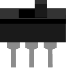
 Design with Toggle Switch in Cirkit Designer
Introduction
A toggle switch is a mechanical switch operated by a lever or handle, allowing the user to open or close a circuit. It is a versatile and reliable component commonly used to control power to devices. Toggle switches are available in various configurations, such as single-pole single-throw (SPST), single-pole double-throw (SPDT), double-pole single-throw (DPST), and double-pole double-throw (DPDT). These configurations make them suitable for a wide range of applications, including household appliances, automotive systems, industrial machinery, and DIY electronics projects.
Explore Projects Built with Toggle Switch
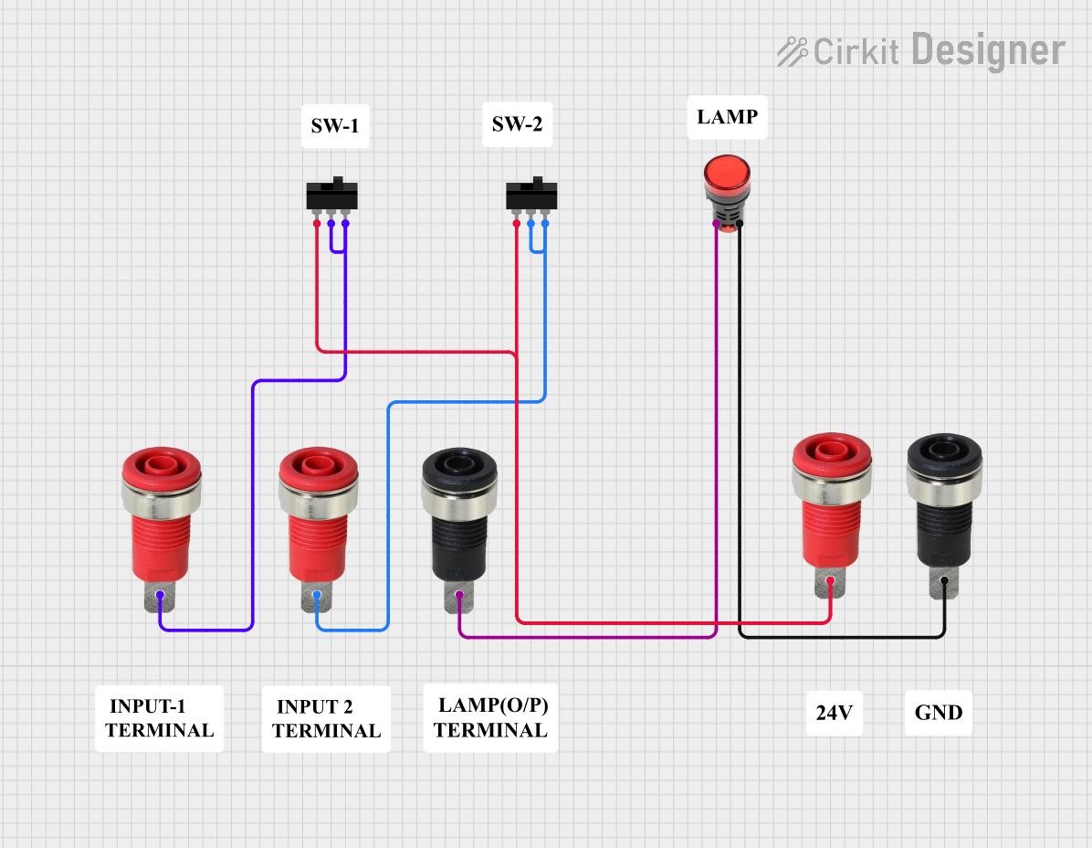 Open Project in Cirkit Designer
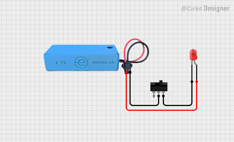 Open Project in Cirkit Designer
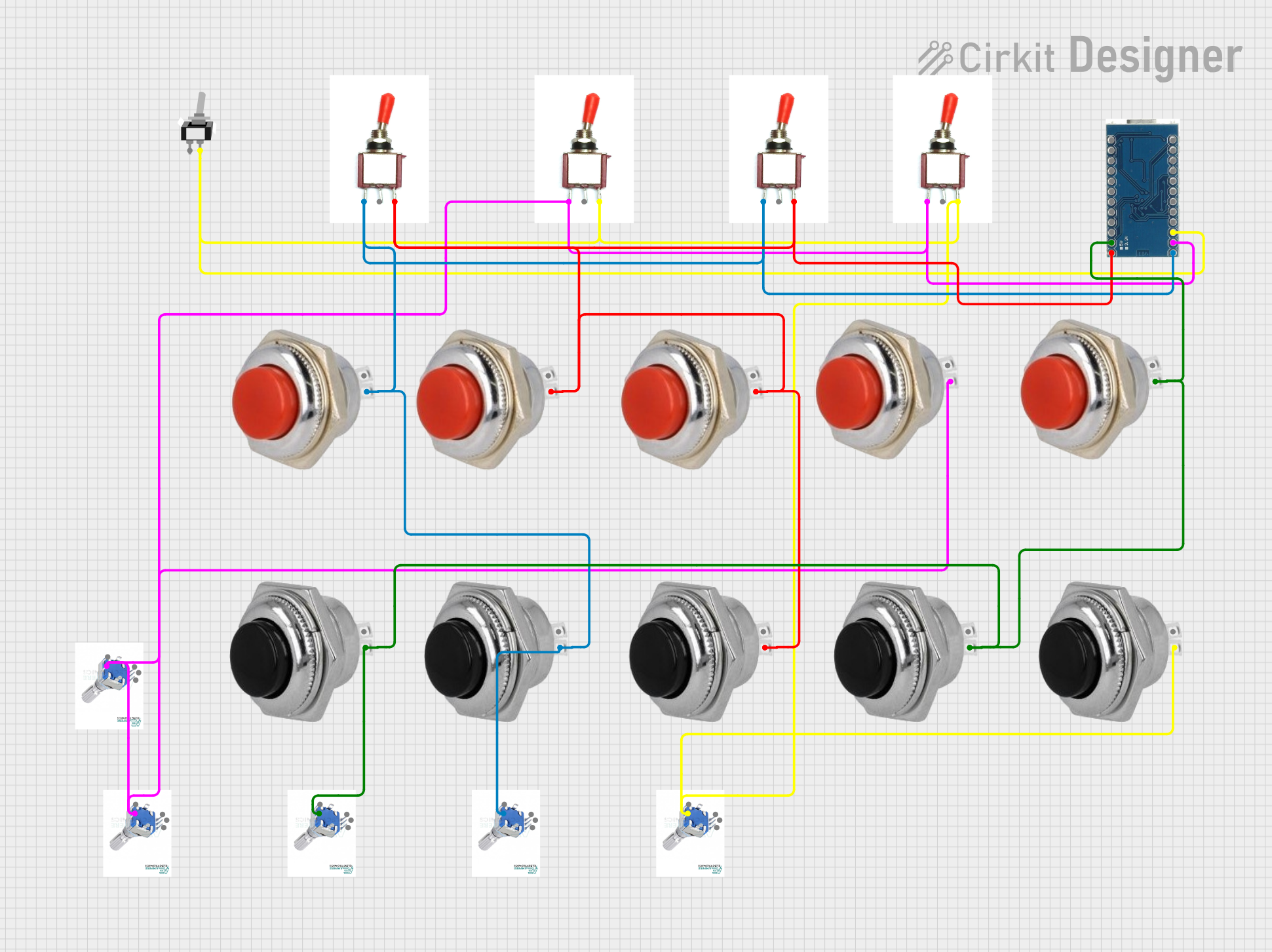 Open Project in Cirkit Designer
 Open Project in Cirkit Designer
Explore Projects Built with Toggle Switch
Open Project in Cirkit DesignerOpen Project in Cirkit DesignerOpen Project in Cirkit DesignerOpen Project in Cirkit DesignerTechnical Specifications
Below are the general technical specifications for a standard toggle switch. Note that specific values may vary depending on the manufacturer and model.
- Voltage Rating: Typically 12V to 250V AC/DC
- Current Rating: 2A to 15A (depending on the switch type)
- Contact Resistance: ≤ 50 mΩ
- Insulation Resistance: ≥ 100 MΩ at 500V DC
- Operating Temperature: -20°C to 85°C
- Mechanical Life: 50,000 to 100,000 cycles
Pin Configuration and Descriptions
The pin configuration of a toggle switch depends on its type. Below are the common configurations:
SPST (Single-Pole Single-Throw)
| Pin Number | Description |
|---|---|
| 1 | Input (connect to power source) |
| 2 | Output (connect to load) |
SPDT (Single-Pole Double-Throw)
| Pin Number | Description |
|---|---|
| 1 | Common (connect to power source) |
| 2 | Normally Closed (NC) |
| 3 | Normally Open (NO) |
DPDT (Double-Pole Double-Throw)
| Pin Number | Description |
|---|---|
| 1 | Common for Pole 1 |
| 2 | Normally Closed (NC) for Pole 1 |
| 3 | Normally Open (NO) for Pole 1 |
| 4 | Common for Pole 2 |
| 5 | Normally Closed (NC) for Pole 2 |
| 6 | Normally Open (NO) for Pole 2 |
Usage Instructions
How to Use a Toggle Switch in a Circuit
- Identify the Type of Toggle Switch: Determine whether the switch is SPST, SPDT, DPST, or DPDT based on your circuit requirements.
- Connect the Pins:
- For SPST: Connect the input pin to the power source and the output pin to the load.
- For SPDT: Connect the common pin to the power source, and choose between the NC or NO pin for the load, depending on the desired behavior.
- For DPDT: Wire each pole independently, following the same logic as SPDT.
- Secure the Switch: Mount the toggle switch in a suitable enclosure or panel to ensure stability and safety.
- Test the Circuit: Verify the connections and test the switch operation to ensure it functions as intended.
Important Considerations and Best Practices
- Voltage and Current Ratings: Always ensure the toggle switch can handle the voltage and current of your circuit to avoid overheating or damage.
- Debouncing: Mechanical switches may cause bouncing, leading to multiple signals. Use a capacitor or software debounce logic in sensitive circuits.
- Safety: When working with high voltages, ensure proper insulation and grounding to prevent electrical hazards.
- Mounting: Use a panel or enclosure to protect the switch from accidental toggling or environmental factors.
Example: Using a Toggle Switch with Arduino UNO
Below is an example of how to use an SPST toggle switch to control an LED with an Arduino UNO.
// Define pin connections
const int toggleSwitchPin = 2; // Pin connected to the toggle switch
const int ledPin = 13;        // Pin connected to the LED

void setup() {
  pinMode(toggleSwitchPin, INPUT_PULLUP); // Set toggle switch pin as input with pull-up
  pinMode(ledPin, OUTPUT);               // Set LED pin as output
}

void loop() {
  int switchState = digitalRead(toggleSwitchPin); // Read the state of the toggle switch

  if (switchState == LOW) { // If the switch is toggled ON (connected to GND)
    digitalWrite(ledPin, HIGH); // Turn the LED ON
  } else {
    digitalWrite(ledPin, LOW);  // Turn the LED OFF
  }
}
Note: The
INPUT_PULLUPmode is used to avoid the need for an external pull-up resistor. When the switch is ON, it connects the pin to GND, resulting in a LOW signal.
Troubleshooting and FAQs
Common Issues
Switch Not Working:
- Cause: Incorrect wiring or loose connections.
- Solution: Double-check the pin connections and ensure they are secure.
Overheating:
- Cause: Exceeding the voltage or current rating of the switch.
- Solution: Use a switch with appropriate ratings for your circuit.
Switch Bouncing:
- Cause: Mechanical contacts causing multiple signals.
- Solution: Add a debounce circuit (e.g., capacitor) or implement software debouncing.
LED Not Responding in Arduino Circuit:
- Cause: Incorrect pin configuration or faulty switch.
- Solution: Verify the Arduino code and ensure the switch is functioning properly.
FAQs
Can I use a toggle switch for AC circuits?
- Yes, as long as the switch is rated for the voltage and current of the AC circuit.
What is the difference between SPST and SPDT?
- SPST has two pins and acts as a simple ON/OFF switch. SPDT has three pins and can toggle between two outputs (NC and NO).
How do I prevent accidental toggling?
- Use a locking toggle switch or mount the switch in a protected enclosure.
Can I use a toggle switch to control multiple devices?
- Yes, a DPDT switch can control two separate circuits simultaneously.
By following this documentation, you can effectively integrate a toggle switch into your projects and troubleshoot common issues with ease.