How to Use Motor Driver 2 Channel: Examples, Pinouts, and Specs
Introduction
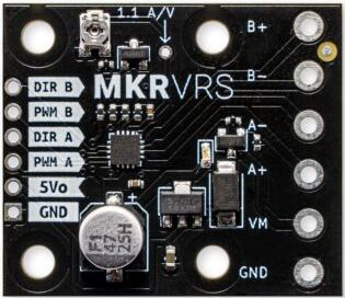
The Makerverse 2-Channel Motor Driver is a versatile and robust electronic component designed to control the direction and speed of two DC motors simultaneously. It is commonly used in robotics, automation projects, and various DIY applications where precise motor control is required.
Explore Projects Built with Motor Driver 2 Channel

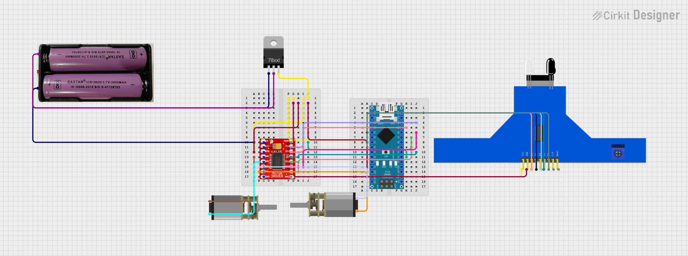

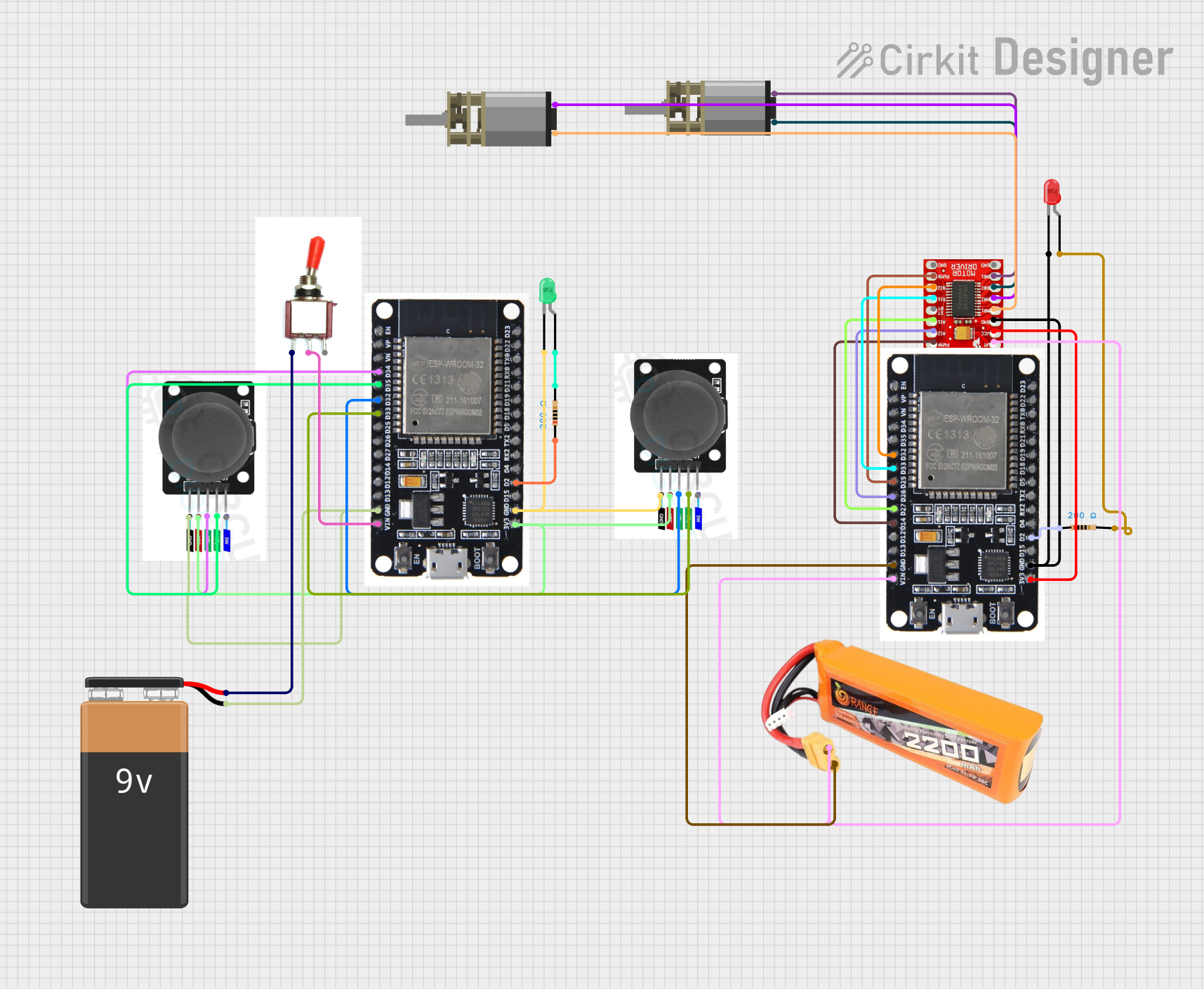
Explore Projects Built with Motor Driver 2 Channel
Common Applications and Use Cases:
- Robotics
- Automated Guided Vehicles (AGVs)
- Hobbyist projects
- Educational platforms for learning electronics and programming
Technical Specifications
Key Technical Details:
- Operating Voltage: Typically ranges from 5V to 12V
- Continuous Current per Channel: Up to 1A (2A peak)
- Logic Voltage: 3.3V to 5V (compatible with most microcontrollers)
- Control Signals: PWM (Pulse Width Modulation) for speed control, digital inputs for direction control
Pin Configuration and Descriptions:
| Pin Number | Pin Name | Description |
|---|---|---|
| 1 | VCC | Connect to the positive terminal of the power supply (5V-12V) |
| 2 | GND | Connect to the ground of the power supply |
| 3 | AIA | Motor A input A; controls the direction |
| 4 | AIB | Motor A input B; controls the direction |
| 5 | PWMA | PWM input for Motor A; controls the speed |
| 6 | BIA | Motor B input A; controls the direction |
| 7 | BIB | Motor B input B; controls the direction |
| 8 | PWMB | PWM input for Motor B; controls the speed |
| 9 | OUTA1 | Output A1; connect to one terminal of Motor A |
| 10 | OUTA2 | Output A2; connect to the other terminal of Motor A |
| 11 | OUTB1 | Output B1; connect to one terminal of Motor B |
| 12 | OUTB2 | Output B2; connect to the other terminal of Motor B |
Usage Instructions
How to Use the Component in a Circuit:
- Connect the power supply to the VCC and GND pins.
- Connect the motor terminals to the OUTA1, OUTA2 for Motor A and OUTB1, OUTB2 for Motor B.
- Connect the control pins (AIA, AIB, PWMA, BIA, BIB, PWMB) to the corresponding pins on your microcontroller, such as an Arduino UNO.
Important Considerations and Best Practices:
- Ensure the power supply voltage and current do not exceed the specifications.
- Use flyback diodes if they are not already included in the driver to protect against voltage spikes.
- Avoid running motors at stall current as it can damage the driver.
- Use PWM signals for speed control and digital HIGH/LOW signals for direction control.
Example Code for Arduino UNO
// Define motor driver pins
#define AIA 2
#define AIB 3
#define PWMA 5 // PWM pin for speed control
#define BIA 4
#define BIB 7
#define PWMB 6 // PWM pin for speed control

void setup() {
  // Set motor driver pins as outputs
  pinMode(AIA, OUTPUT);
  pinMode(AIB, OUTPUT);
  pinMode(PWMA, OUTPUT);
  pinMode(BIA, OUTPUT);
  pinMode(BIB, OUTPUT);
  pinMode(PWMB, OUTPUT);
}

void loop() {
  // Set Motor A to spin in one direction at full speed
  digitalWrite(AIA, HIGH);
  digitalWrite(AIB, LOW);
  analogWrite(PWMA, 255); // Full speed

  // Set Motor B to spin in the opposite direction at half speed
  digitalWrite(BIA, LOW);
  digitalWrite(BIB, HIGH);
  analogWrite(PWMB, 127); // Half speed

  delay(2000); // Run motors for 2 seconds

  // Stop both motors
  digitalWrite(AIA, LOW);
  digitalWrite(AIB, LOW);
  digitalWrite(BIA, LOW);
  digitalWrite(BIB, LOW);
  analogWrite(PWMA, 0); // Stop Motor A
  analogWrite(PWMB, 0); // Stop Motor B

  delay(1000); // Wait for 1 second
}
Troubleshooting and FAQs
Common Issues Users Might Face:
- Motor not spinning: Check connections, ensure power supply is within specifications, and verify that control signals are being sent from the microcontroller.
- Motor spinning in one direction only: Ensure that both direction control pins (AIA/AIB or BIA/BIB) are correctly connected and being controlled.
- Overheating: This can be caused by overloading the motor driver. Make sure the current draw is within the specified limits.
Solutions and Tips for Troubleshooting:
- Double-check wiring and connections.
- Use a multimeter to verify the voltage at the motor driver's power supply and output pins.
- Ensure that the PWM signal is within the correct range for speed control.
- If the motor driver has thermal protection, allow it to cool down before attempting to use it again.
FAQs:
Q: Can I control stepper motors with this driver? A: No, this driver is designed for DC motors. Stepper motors require a different type of driver.
Q: What should I do if the motor driver gets hot during operation? A: Ensure that the current draw is within the safe operating limits and check for any shorts. Consider adding a heat sink or improving ventilation if necessary.
Q: Can I use a single power supply for both the motor driver and the microcontroller? A: Yes, as long as the power supply meets the voltage and current requirements for both the motor driver and the microcontroller without exceeding the maximum ratings.