How to Use Movitrac LTE-B+: Examples, Pinouts, and Specs
Introduction
The Movitrac LTE-B+ is a versatile frequency inverter manufactured by SEW (Part ID: MCLTEB0015-2B1-4-00). It is designed for controlling three-phase AC motors, offering advanced features such as energy efficiency, precise speed control, and robust communication options. This component is ideal for applications requiring reliable motor control in industrial environments.
Explore Projects Built with Movitrac LTE-B+


Explore Projects Built with Movitrac LTE-B+
Common Applications and Use Cases
- Conveyor systems in manufacturing plants
- Pump and fan control in HVAC systems
- Material handling equipment
- Energy-efficient motor control in industrial automation
- Speed and torque control for three-phase motors
Technical Specifications
Key Technical Details
| Parameter | Value |
|---|---|
| Input Voltage Range | 1-phase: 200–240 V AC ±10% |
| Output Voltage Range | 3-phase: 0–240 V AC |
| Output Frequency Range | 0–120 Hz |
| Rated Power | 1.5 kW |
| Rated Current | 7.0 A |
| Control Method | V/f (Voltage/Frequency) control, Vector control |
| Communication Interfaces | RS485 (Modbus RTU) |
| Protection Class | IP20 |
| Operating Temperature Range | -10°C to +50°C |
| Dimensions (H x W x D) | 173 mm x 73 mm x 143 mm |
| Weight | 1.1 kg |
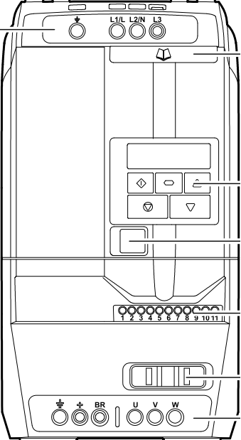
Pin Configuration and Descriptions
The Movitrac LTE-B+ features a terminal block for wiring connections. Below is the pin configuration:
Power Terminals
| Pin No. | Label | Description |
|---|---|---|
| L | L | Line input (AC power supply) |
| N | N | Neutral input (AC power supply) |
| PE | PE | Protective Earth (ground) |
| U | U | Output to motor phase U |
| V | V | Output to motor phase V |
| W | W | Output to motor phase W |
Control Terminals
| Pin No. | Label | Description |
|---|---|---|
| 1 | +24V | 24V DC supply for control circuits |
| 2 | GND | Ground for control circuits |
| 3 | DI1 | Digital input 1 (e.g., Start/Stop) |
| 4 | DI2 | Digital input 2 (e.g., Forward/Reverse) |
| 5 | AI1 | Analog input 1 (0–10V or 4–20mA) |
| 6 | AO1 | Analog output 1 (e.g., motor speed feedback) |
| 7 | RS485+ | RS485 communication (positive) |
| 8 | RS485- | RS485 communication (negative) |
Usage Instructions
How to Use the Movitrac LTE-B+ in a Circuit
- Power Connection: Connect the AC power supply to the
LandNterminals. Ensure thePEterminal is properly grounded for safety. - Motor Connection: Connect the three-phase motor to the
U,V, andWterminals. - Control Wiring: Use the control terminals to connect external devices such as switches, sensors, or a PLC. For example:
- Connect a Start/Stop switch to
DI1. - Use
AI1for speed control via a potentiometer or analog signal.
- Connect a Start/Stop switch to
- Communication Setup: If using Modbus RTU, connect the RS485+ and RS485- terminals to the communication network.
- Parameter Configuration: Use the built-in keypad or software to configure parameters such as motor type, speed range, and control mode.
Important Considerations and Best Practices
- Ensure the input voltage matches the specified range (200–240 V AC).
- Use proper cable shielding and grounding to minimize electrical noise.
- Avoid exceeding the rated power and current limits to prevent damage.
- Regularly inspect and clean the inverter to ensure proper ventilation and cooling.
- For safety, always disconnect power before performing any wiring or maintenance.
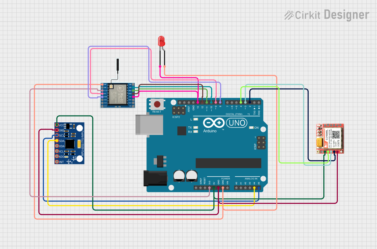
Example: Controlling the Movitrac LTE-B+ with an Arduino UNO
The Movitrac LTE-B+ can be controlled via Modbus RTU using an Arduino UNO. Below is an example code snippet:
#include <ModbusMaster.h>

// Create ModbusMaster object
ModbusMaster node;

void setup() {
  Serial.begin(9600); // Initialize serial communication
  node.begin(1, Serial); // Set Modbus slave ID to 1

  // Configure digital pin for Start/Stop control
  pinMode(7, OUTPUT);
  digitalWrite(7, LOW); // Ensure motor is stopped initially
}

void loop() {
  // Example: Set motor speed to 50% (assuming 0–100% range)
  uint16_t speedValue = 500; // 50% of max speed (scaled to 0–1000)

  // Write speed value to Modbus register (e.g., register 0x2000)
  uint8_t result = node.writeSingleRegister(0x2000, speedValue);

  if (result == node.ku8MBSuccess) {
    Serial.println("Speed set successfully!");
  } else {
    Serial.println("Failed to set speed.");
  }

  delay(1000); // Wait for 1 second before next operation
}
Note: Ensure the Modbus register addresses match the Movitrac LTE-B+ documentation. Use a suitable RS485-to-TTL converter to connect the Arduino to the inverter.
Troubleshooting and FAQs
Common Issues and Solutions
Inverter Does Not Power On
- Cause: Incorrect wiring or no power supply.
- Solution: Verify the AC input voltage and check the wiring connections.
Motor Does Not Start
- Cause: Incorrect parameter settings or control signal missing.
- Solution: Check the Start/Stop signal on
DI1and verify motor parameters.
Overload or Overcurrent Fault
- Cause: Motor is drawing excessive current.
- Solution: Ensure the motor is not overloaded and check for short circuits.
Communication Failure
- Cause: Incorrect RS485 wiring or settings.
- Solution: Verify the RS485 connections and ensure the baud rate and slave ID match.
FAQs
Q: Can the Movitrac LTE-B+ control single-phase motors?
A: No, it is designed for three-phase AC motors only.Q: How do I reset the inverter to factory settings?
A: Refer to the user manual for the specific parameter reset procedure.Q: What is the maximum cable length for RS485 communication?
A: The maximum recommended length is 1200 meters, depending on the baud rate and cable quality.Q: Can I use the Movitrac LTE-B+ outdoors?
A: No, the inverter has an IP20 protection class and must be installed in a dry, indoor environment.
By following this documentation, users can effectively integrate and operate the Movitrac LTE-B+ in their applications.