
How to Use XPORT-DIRECT: Examples, Pinouts, and Specs
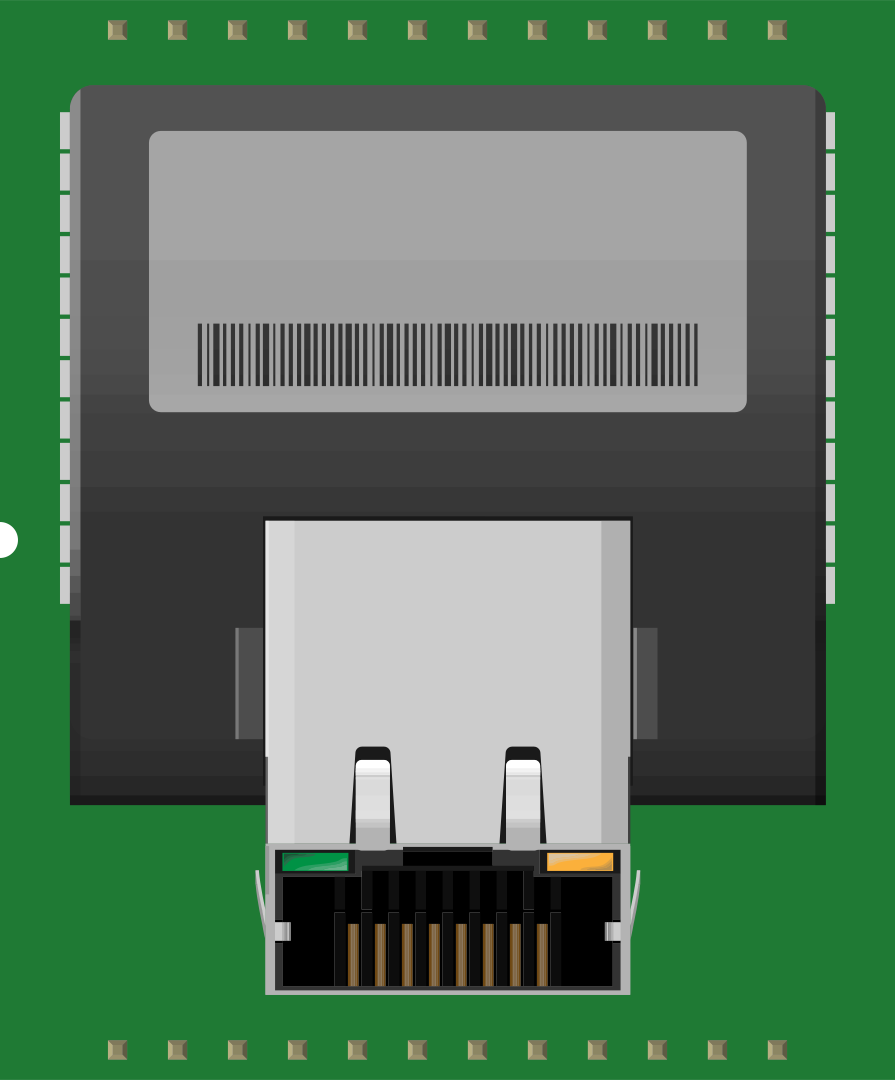
 Design with XPORT-DIRECT in Cirkit Designer
Introduction
The XPORT-DIRECT by Lantronix is a compact, high-performance Ethernet module designed to simplify the integration of network connectivity into embedded systems. This module provides a reliable and cost-effective solution for enabling Ethernet communication in a wide range of applications. Its small form factor and robust design make it ideal for use in industrial automation, IoT devices, remote monitoring systems, and other embedded applications requiring network connectivity.
Explore Projects Built with XPORT-DIRECT
 Open Project in Cirkit Designer
 Open Project in Cirkit Designer
 Open Project in Cirkit Designer
 Open Project in Cirkit Designer
Explore Projects Built with XPORT-DIRECT
Open Project in Cirkit DesignerOpen Project in Cirkit DesignerOpen Project in Cirkit DesignerOpen Project in Cirkit DesignerCommon Applications
- Industrial automation and control systems
- IoT (Internet of Things) devices
- Remote monitoring and data logging
- Home and building automation
- Medical devices requiring network communication
Technical Specifications
Key Technical Details
| Parameter | Value |
|---|---|
| Manufacturer | Lantronix |
| Part ID | XPORT-DIRECT |
| Network Interface | 10/100 Mbps Ethernet |
| Input Voltage Range | 3.3V DC |
| Power Consumption | 180 mA (typical) |
| Operating Temperature | -40°C to +85°C |
| Dimensions | 33.9 mm x 16.25 mm x 13.5 mm |
| Protocol Support | TCP/IP, UDP, HTTP, DHCP, ARP, ICMP, etc. |
| Connector Type | RJ45 Ethernet |
Pin Configuration and Descriptions
The XPORT-DIRECT module has a 10-pin header for interfacing with the host system. Below is the pin configuration:
| Pin Number | Pin Name | Description |
|---|---|---|
| 1 | GND | Ground |
| 2 | VCC | 3.3V Power Supply Input |
| 3 | TXD | Transmit Data (UART Output) |
| 4 | RXD | Receive Data (UART Input) |
| 5 | RTS | Request to Send (UART Control) |
| 6 | CTS | Clear to Send (UART Control) |
| 7 | RESET | Active Low Reset Input |
| 8 | STATUS | Status Indicator Output |
| 9 | LINK_LED | Ethernet Link LED Output |
| 10 | ACT_LED | Ethernet Activity LED Output |
Usage Instructions
How to Use the XPORT-DIRECT in a Circuit
- Power Supply: Connect the VCC pin to a regulated 3.3V DC power supply and the GND pin to the ground of your circuit.
- UART Communication: Use the TXD and RXD pins to establish UART communication with your microcontroller or host system. Optionally, connect RTS and CTS for hardware flow control.
- Ethernet Connection: Plug an Ethernet cable into the RJ45 connector to enable network communication.
- Reset: Connect the RESET pin to a push-button or microcontroller GPIO for manual or software-controlled resets.
- LED Indicators: Use the LINK_LED and ACT_LED pins to monitor Ethernet link and activity status.
Important Considerations
- Ensure the power supply is stable and within the specified voltage range (3.3V DC).
- Use proper decoupling capacitors near the VCC pin to minimize noise.
- If using the module in a noisy environment, consider adding shielding to reduce electromagnetic interference (EMI).
- Configure the module's network settings (e.g., IP address, subnet mask) using the provided software tools or via UART commands.
Example: Connecting XPORT-DIRECT to an Arduino UNO
Below is an example of how to connect the XPORT-DIRECT module to an Arduino UNO for basic UART communication:
Wiring Diagram
| XPORT-DIRECT Pin | Arduino UNO Pin |
|---|---|
| GND | GND |
| VCC | 3.3V |
| TXD | Pin 0 (RX) |
| RXD | Pin 1 (TX) |
| RESET | Digital Pin 2 |
Arduino Code Example
// Example code to send and receive data via XPORT-DIRECT module
// Connect TXD and RXD of XPORT-DIRECT to Arduino's RX and TX pins respectively.

void setup() {
  Serial.begin(9600); // Initialize UART communication at 9600 baud rate
  pinMode(2, OUTPUT); // Set pin 2 as output for RESET control
  digitalWrite(2, HIGH); // Ensure RESET pin is not active
  delay(100); // Wait for the module to initialize
}

void loop() {
  // Send data to XPORT-DIRECT
  Serial.println("Hello, XPORT-DIRECT!");

  // Check if data is received from XPORT-DIRECT
  if (Serial.available() > 0) {
    String receivedData = Serial.readString();
    Serial.print("Received: ");
    Serial.println(receivedData);
  }

  delay(1000); // Wait for 1 second before sending the next message
}
Troubleshooting and FAQs
Common Issues and Solutions
No Ethernet Connectivity
- Ensure the Ethernet cable is securely connected to the RJ45 port.
- Verify that the network settings (IP address, subnet mask, etc.) are correctly configured.
- Check the LINK_LED and ACT_LED pins for activity.
UART Communication Not Working
- Confirm that the TXD and RXD pins are correctly connected to the host system.
- Ensure the baud rate matches between the XPORT-DIRECT and the host system.
- Check for proper grounding between the module and the host system.
Module Not Powering On
- Verify that the power supply provides a stable 3.3V DC.
- Check for loose connections or damaged wires.
Reset Pin Not Functioning
- Ensure the RESET pin is pulled low for at least 100 ms to trigger a reset.
- Verify that the pin is not floating when not in use.
FAQs
Q: Can the XPORT-DIRECT module be powered with 5V?
A: No, the module requires a regulated 3.3V DC power supply. Using 5V may damage the module.
Q: Does the module support DHCP?
A: Yes, the XPORT-DIRECT supports DHCP for automatic IP address assignment.
Q: How can I update the firmware?
A: Firmware updates can be performed via the Ethernet interface using the Lantronix DeviceInstaller software.
Q: Is the module compatible with SPI or I2C?
A: No, the XPORT-DIRECT communicates using UART for host interfacing. SPI and I2C are not supported.