Cirkit Designer Logo
Cirkit Designer
Your all-in-one circuit design IDE
Home / 
Component Documentation

How to Use GPS: Examples, Pinouts, and Specs

Image of GPS
Cirkit Designer LogoDesign with GPS in Cirkit Designer

Introduction

A Global Positioning System (GPS) receiver determines the precise location of an object on Earth using signals from satellites. It calculates latitude, longitude, altitude, and time by analyzing data from multiple satellites in orbit. GPS modules are widely used in navigation systems, tracking devices, drones, and IoT applications. They are essential for applications requiring real-time location data, such as vehicle tracking, geofencing, and outdoor navigation.

Explore Projects Built with GPS

Use Cirkit Designer to design, explore, and prototype these projects online. Some projects support real-time simulation. Click "Open Project" to start designing instantly!
ESP32-Based GPS Tracker with OLED Display and Telegram Integration
Image of Yoon: A project utilizing GPS in a practical application
This circuit is a GPS-based tracking system that uses an ESP32 microcontroller to receive GPS data from a NEO 6M module and display the coordinates on a 1.3" OLED screen. It also features WiFi connectivity to send location updates to a remote server, potentially for applications such as asset tracking or navigation assistance.
Cirkit Designer LogoOpen Project in Cirkit Designer
ESP32-Based GPS Tracker with OLED Display and Firebase Integration
Image of ecs: A project utilizing GPS in a practical application
This circuit is a GPS tracking system that uses an ESP32 microcontroller to read location data from a NEO-6M GPS module and display information on a 0.96" OLED screen. The system is powered by a 2000mAh battery with a lithium-ion charger, and it uploads the GPS data to Firebase via WiFi. Additional components include an MPU6050 accelerometer/gyroscope for motion sensing and a buzzer for alerts.
Cirkit Designer LogoOpen Project in Cirkit Designer
Arduino Nano GPS Tracker with GSM and OLED Display
Image of Smart GPS Tracker: A project utilizing GPS in a practical application
This circuit is a GPS tracking system that uses an Arduino Nano to interface with a SIM800L GSM module, a GPS NEO 6M module, and a 1.3-inch OLED display. The Arduino collects GPS data, displays it on the OLED screen, and sends the coordinates via SMS using the GSM module.
Cirkit Designer LogoOpen Project in Cirkit Designer
Arduino UNO-Based GPS and GSM-Enabled Vibration Sensor System with Motor Control
Image of gps based accident detection and alert system: A project utilizing GPS in a practical application
This circuit is a GPS-based tracking system with vibration detection and motor control capabilities. It uses an Arduino UNO to interface with a Neo 6M GPS module for location data, a Sim800l module for GSM communication, an ADXL345 accelerometer for motion sensing, and an SW-420 vibration sensor to detect vibrations. The system also includes a motor driver to control two DC motors and a buzzer for alerts, all powered by a 5V battery.
Cirkit Designer LogoOpen Project in Cirkit Designer

Explore Projects Built with GPS

Use Cirkit Designer to design, explore, and prototype these projects online. Some projects support real-time simulation. Click "Open Project" to start designing instantly!
Image of Yoon: A project utilizing GPS in a practical application
ESP32-Based GPS Tracker with OLED Display and Telegram Integration
This circuit is a GPS-based tracking system that uses an ESP32 microcontroller to receive GPS data from a NEO 6M module and display the coordinates on a 1.3" OLED screen. It also features WiFi connectivity to send location updates to a remote server, potentially for applications such as asset tracking or navigation assistance.
Cirkit Designer LogoOpen Project in Cirkit Designer
Image of ecs: A project utilizing GPS in a practical application
ESP32-Based GPS Tracker with OLED Display and Firebase Integration
This circuit is a GPS tracking system that uses an ESP32 microcontroller to read location data from a NEO-6M GPS module and display information on a 0.96" OLED screen. The system is powered by a 2000mAh battery with a lithium-ion charger, and it uploads the GPS data to Firebase via WiFi. Additional components include an MPU6050 accelerometer/gyroscope for motion sensing and a buzzer for alerts.
Cirkit Designer LogoOpen Project in Cirkit Designer
Image of Smart GPS Tracker: A project utilizing GPS in a practical application
Arduino Nano GPS Tracker with GSM and OLED Display
This circuit is a GPS tracking system that uses an Arduino Nano to interface with a SIM800L GSM module, a GPS NEO 6M module, and a 1.3-inch OLED display. The Arduino collects GPS data, displays it on the OLED screen, and sends the coordinates via SMS using the GSM module.
Cirkit Designer LogoOpen Project in Cirkit Designer
Image of gps based accident detection and alert system: A project utilizing GPS in a practical application
Arduino UNO-Based GPS and GSM-Enabled Vibration Sensor System with Motor Control
This circuit is a GPS-based tracking system with vibration detection and motor control capabilities. It uses an Arduino UNO to interface with a Neo 6M GPS module for location data, a Sim800l module for GSM communication, an ADXL345 accelerometer for motion sensing, and an SW-420 vibration sensor to detect vibrations. The system also includes a motor driver to control two DC motors and a buzzer for alerts, all powered by a 5V battery.
Cirkit Designer LogoOpen Project in Cirkit Designer

Technical Specifications

Below are the general technical specifications for a typical GPS module:

  • Input Voltage: 3.3V to 5V
  • Operating Current: 20mA to 50mA
  • Communication Protocol: UART (Universal Asynchronous Receiver-Transmitter)
  • Baud Rate: 9600 bps (default, configurable)
  • Position Accuracy: ±2.5 meters (typical)
  • Update Rate: 1Hz to 10Hz
  • Antenna: External or built-in (active or passive)
  • Operating Temperature: -40°C to +85°C

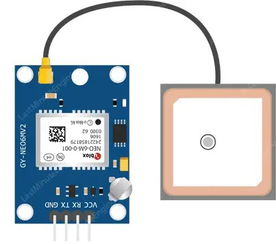
Pin Configuration and Descriptions

The pinout of a typical GPS module is as follows:

Pin Name Description
VCC Power supply input (3.3V to 5V).
GND Ground connection.
TX Transmit pin for UART communication. Sends GPS data to the microcontroller.
RX Receive pin for UART communication. Receives commands from the microcontroller.
PPS Pulse Per Second output for precise timing (optional, not available on all modules).

Usage Instructions

How to Use the GPS Module in a Circuit

  1. Power the Module: Connect the VCC pin to a 3.3V or 5V power source and the GND pin to ground.
  2. Connect UART Pins:
    • Connect the TX pin of the GPS module to the RX pin of the microcontroller (e.g., Arduino UNO).
    • Connect the RX pin of the GPS module to the TX pin of the microcontroller.
  3. Antenna Placement: If the module uses an external antenna, ensure it is placed in an open area with a clear view of the sky for optimal satellite signal reception.
  4. Configure Baud Rate: Most GPS modules use a default baud rate of 9600 bps. Ensure your microcontroller's UART settings match this baud rate.
  5. Read GPS Data: The module outputs NMEA (National Marine Electronics Association) sentences, which contain location, time, and other data. Parse these sentences to extract the required information.

Important Considerations and Best Practices

  • Signal Reception: GPS modules require a clear line of sight to satellites. Avoid using them indoors or in areas with heavy obstructions.
  • Power Supply: Use a stable power source to avoid interruptions in GPS data.
  • Antenna Type: For better performance, use an active antenna if the module supports it.
  • Data Parsing: Use libraries or software tools to parse NMEA sentences efficiently.

Example: Connecting GPS to Arduino UNO

Below is an example of how to connect and use a GPS module with an Arduino UNO:

Circuit Connections

  • GPS VCC → Arduino 5V
  • GPS GND → Arduino GND
  • GPS TX → Arduino RX (Pin 0)
  • GPS RX → Arduino TX (Pin 1)

Arduino Code

#include <SoftwareSerial.h>

// Create a SoftwareSerial object to communicate with the GPS module
SoftwareSerial gpsSerial(4, 3); // RX = Pin 4, TX = Pin 3

void setup() {
  Serial.begin(9600);          // Initialize Serial Monitor at 9600 bps
  gpsSerial.begin(9600);       // Initialize GPS module at 9600 bps
  Serial.println("GPS Module Test");
}

void loop() {
  while (gpsSerial.available()) {
    char c = gpsSerial.read(); // Read data from GPS module
    Serial.print(c);           // Print GPS data to Serial Monitor
  }
}

Note: The above code uses SoftwareSerial to avoid conflicts with the Arduino's hardware UART pins.

Troubleshooting and FAQs

Common Issues and Solutions

  1. No GPS Data Output:

    • Ensure the GPS module is powered correctly and the connections are secure.
    • Verify that the baud rate of the GPS module matches the microcontroller's UART settings.
  2. Poor Signal Reception:

    • Place the GPS antenna in an open area with a clear view of the sky.
    • Avoid using the module near electronic devices that may cause interference.
  3. Incorrect Data Parsing:

    • Use a GPS library (e.g., TinyGPS++ for Arduino) to simplify NMEA sentence parsing.
    • Ensure the microcontroller's UART buffer is large enough to handle incoming data.
  4. Module Not Responding:

    • Check the power supply voltage and current requirements.
    • Verify that the TX and RX pins are connected correctly.

FAQs

Q: Can I use the GPS module indoors?
A: GPS modules generally perform poorly indoors due to limited satellite visibility. Use them in open areas for best results.

Q: How do I increase the update rate of the GPS module?
A: Some GPS modules allow you to configure the update rate via specific commands. Refer to the module's datasheet for details.

Q: What is the purpose of the PPS pin?
A: The PPS (Pulse Per Second) pin provides a precise timing signal, often used in time-sensitive applications.

Q: Can I use the GPS module with a 3.3V microcontroller?
A: Yes, most GPS modules support 3.3V operation. Check the module's datasheet to confirm compatibility.