How to Use sensor vbord: Examples, Pinouts, and Specs
Introduction
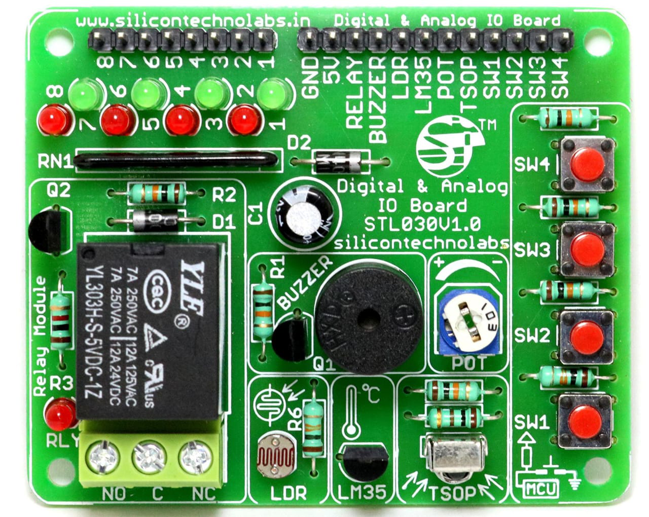
The Sensor Vbord, manufactured by JJ (Part ID: JJ), is a versatile sensor designed for detecting and measuring various physical parameters such as temperature, humidity, pressure, or motion. It is commonly integrated into circuits for monitoring and control applications, making it an essential component in IoT devices, industrial automation, and environmental monitoring systems.
Explore Projects Built with sensor vbord

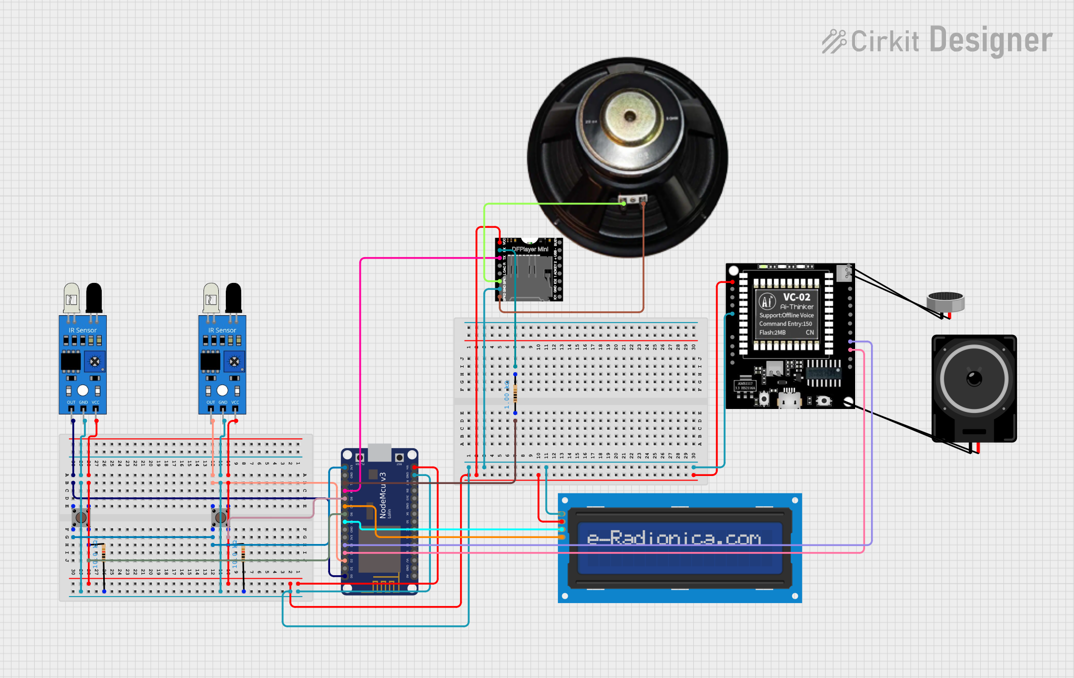
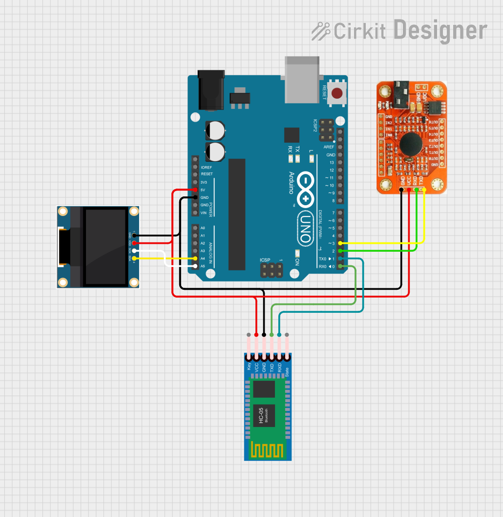

Explore Projects Built with sensor vbord
Common Applications and Use Cases
- IoT Devices: Used for real-time data collection in smart homes and connected devices.
- Industrial Automation: Monitors environmental conditions to optimize processes.
- Environmental Monitoring: Measures parameters like temperature and humidity in weather stations.
- Robotics: Provides sensory input for autonomous navigation and decision-making.
- Consumer Electronics: Integrated into devices like smartphones and wearables for enhanced functionality.
Technical Specifications
The Sensor Vbord is designed to operate efficiently in a wide range of environments. Below are its key technical details:
Key Technical Details
| Parameter | Value |
|---|---|
| Operating Voltage | 3.3V to 5V |
| Operating Current | 10mA (typical) |
| Measurement Range | Depends on the specific sensor type (e.g., -40°C to 85°C for temperature) |
| Communication Protocol | I2C or Analog Output |
| Operating Temperature | -40°C to 85°C |
| Dimensions | 25mm x 15mm x 5mm |
Pin Configuration and Descriptions
The Sensor Vbord has a 4-pin interface for easy integration into circuits. Below is the pinout:
| Pin Number | Pin Name | Description |
|---|---|---|
| 1 | VCC | Power supply input (3.3V to 5V) |
| 2 | GND | Ground connection |
| 3 | DATA | Data output (analog or I2C data line) |
| 4 | CLK | Clock line for I2C communication (if applicable) |
Usage Instructions
The Sensor Vbord is straightforward to use and can be integrated into a variety of circuits. Follow the steps below to use it effectively:
How to Use the Sensor Vbord in a Circuit
- Power the Sensor: Connect the VCC pin to a 3.3V or 5V power source and the GND pin to the ground.
- Connect the Data Line: If using analog output, connect the DATA pin to an analog input pin on your microcontroller. For I2C communication, connect the DATA and CLK pins to the corresponding I2C pins on your microcontroller.
- Read Sensor Data: Use the appropriate library or code to read data from the sensor. For analog output, use an ADC (Analog-to-Digital Converter) to interpret the signal.
Important Considerations and Best Practices
- Power Supply: Ensure the power supply voltage matches the sensor's operating range to avoid damage.
- Pull-Up Resistors: For I2C communication, use pull-up resistors (typically 4.7kΩ) on the DATA and CLK lines.
- Environmental Factors: Protect the sensor from extreme conditions like water or dust unless it is specifically rated for such environments.
- Calibration: Some applications may require calibration to ensure accurate measurements.
Example Code for Arduino UNO
Below is an example of how to use the Sensor Vbord with an Arduino UNO via analog output:
// Example code for reading analog data from Sensor Vbord
const int sensorPin = A0; // Connect the DATA pin of Sensor Vbord to A0
int sensorValue = 0;      // Variable to store the sensor reading

void setup() {
  Serial.begin(9600); // Initialize serial communication at 9600 baud
}

void loop() {
  sensorValue = analogRead(sensorPin); // Read the analog value from the sensor
  Serial.print("Sensor Value: ");
  Serial.println(sensorValue); // Print the sensor value to the Serial Monitor
  delay(1000); // Wait for 1 second before the next reading
}
For I2C communication, use the appropriate library (e.g., Wire.h) and refer to the sensor's datasheet for specific commands.
Troubleshooting and FAQs
Common Issues and Solutions
No Data Output:
- Cause: Incorrect wiring or loose connections.
- Solution: Double-check the wiring and ensure all connections are secure.
Inaccurate Readings:
- Cause: Sensor not calibrated or exposed to extreme conditions.
- Solution: Calibrate the sensor and ensure it is used within its specified operating range.
I2C Communication Failure:
- Cause: Missing pull-up resistors or incorrect I2C address.
- Solution: Add pull-up resistors to the DATA and CLK lines and verify the I2C address.
Overheating:
- Cause: Exceeding the operating voltage or current.
- Solution: Use a regulated power supply within the specified range.
FAQs
Q1: Can the Sensor Vbord be used with a 3.3V microcontroller?
A1: Yes, the Sensor Vbord supports an operating voltage range of 3.3V to 5V, making it compatible with 3.3V microcontrollers.
Q2: Does the Sensor Vbord require an external library for Arduino?
A2: For analog output, no library is required. For I2C communication, you may need to use the Wire.h library or a sensor-specific library.
Q3: How do I protect the sensor in harsh environments?
A3: Use a protective enclosure or coating designed for the specific environmental conditions.
Q4: Can multiple Sensor Vbord units be connected to the same microcontroller?
A4: Yes, for I2C communication, multiple sensors can share the same bus, provided each has a unique address.
By following this documentation, you can effectively integrate and use the Sensor Vbord in your projects.