How to Use TDS sensor : Examples, Pinouts, and Specs

Introduction
A TDS (Total Dissolved Solids) sensor measures the concentration of dissolved solids in water, providing an indication of water quality and purity. It is widely used in applications such as water filtration systems, aquariums, hydroponics, and environmental monitoring. By measuring the electrical conductivity of water, the TDS sensor estimates the total amount of dissolved ions, such as salts, minerals, and metals, in parts per million (ppm).
Explore Projects Built with TDS sensor
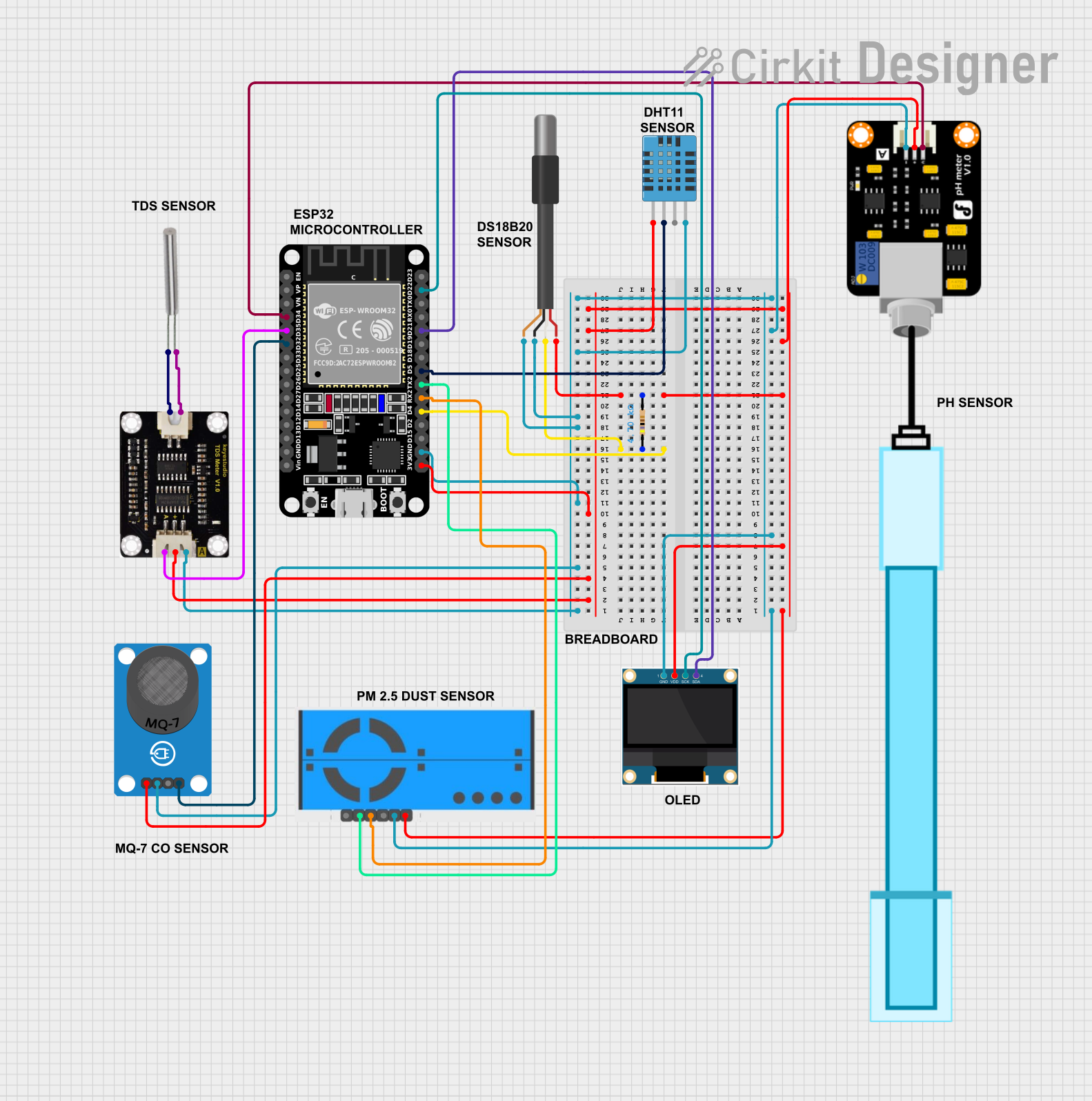
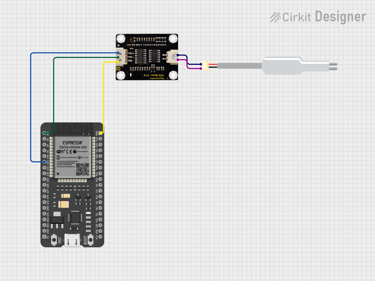
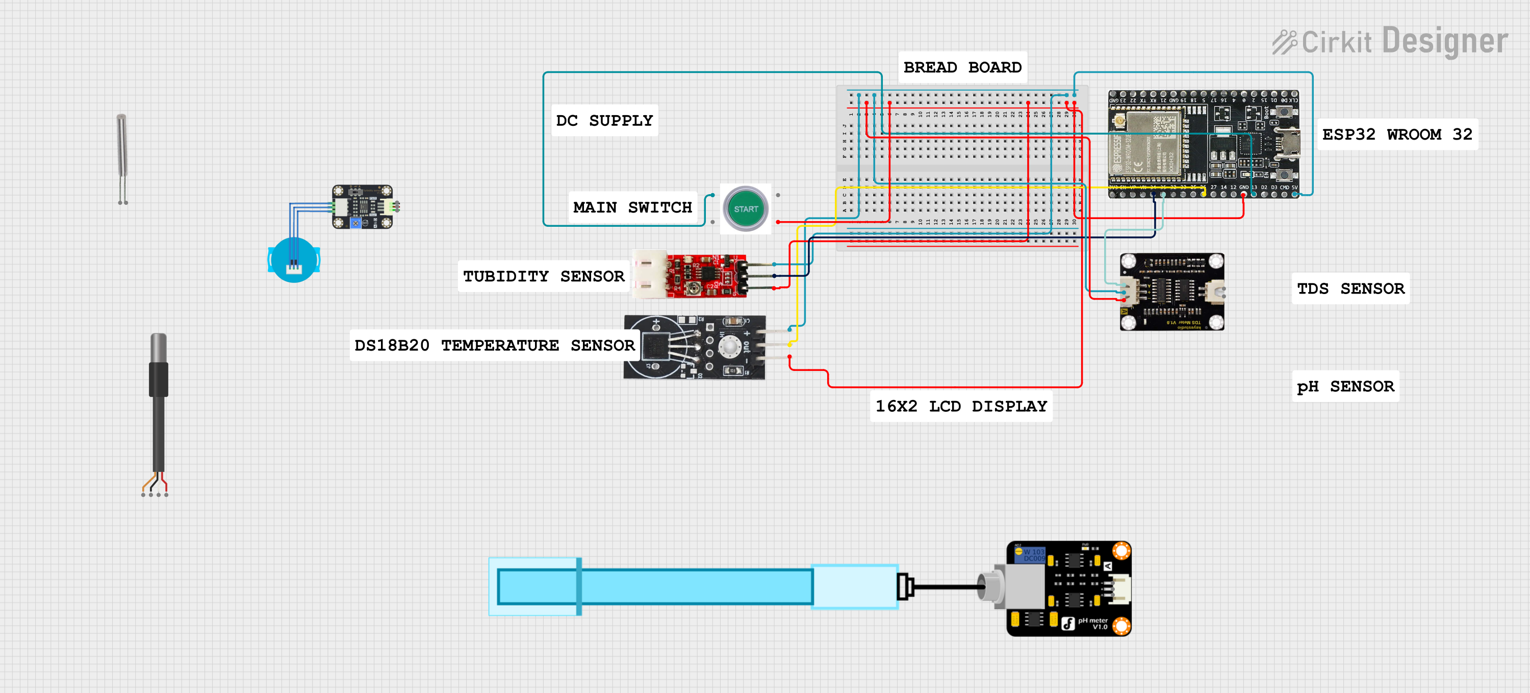
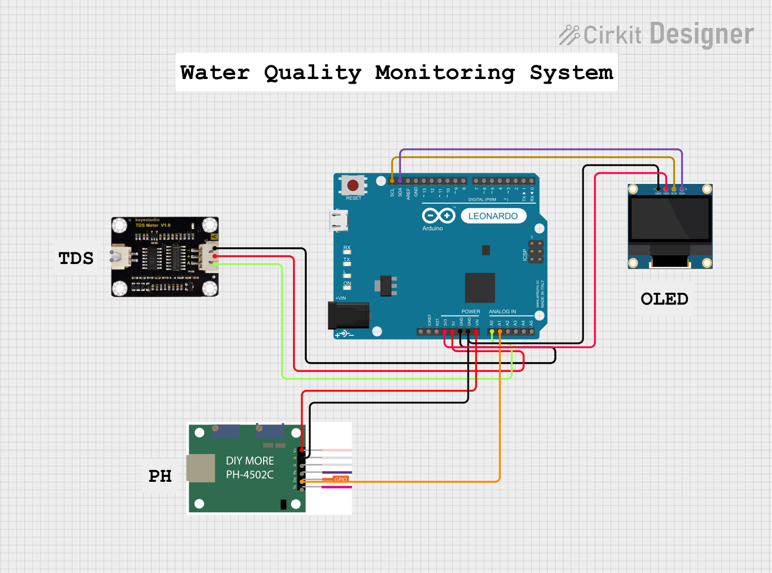
Explore Projects Built with TDS sensor
Technical Specifications
Below are the key technical details and pin configuration for a typical TDS sensor module:
Key Technical Details
- Input Voltage: 3.3V to 5.0V DC
- Output Signal: Analog voltage (proportional to TDS value)
- Measurement Range: 0 to 1000 ppm (can vary by model)
- Accuracy: ±10% of the measured value
- Temperature Compensation: Built-in (some models)
- Probe Material: Stainless steel
- Operating Temperature: 0°C to 60°C
- Cable Length: Typically 1 meter (varies by model)
Pin Configuration
The TDS sensor module typically has three pins for connection:
| Pin | Name | Description |
|---|---|---|
| 1 | VCC | Power supply input (3.3V to 5.0V DC) |
| 2 | GND | Ground connection |
| 3 | AOUT | Analog output signal, proportional to the TDS value (connects to an ADC pin) |
Usage Instructions
How to Use the TDS Sensor in a Circuit
Connect the Sensor:
- Connect the VCC pin of the TDS sensor module to the 5V pin of your microcontroller (e.g., Arduino UNO).
- Connect the GND pin to the ground (GND) of the microcontroller.
- Connect the AOUT pin to an analog input pin (e.g., A0) on the microcontroller.
Place the Probe:
- Submerge the stainless steel probe into the water sample. Ensure the probe is fully immersed but avoid submerging the module itself.
Calibrate the Sensor:
- Use a known TDS solution (e.g., 342 ppm calibration solution) to calibrate the sensor for accurate readings.
Read the Output:
- The sensor outputs an analog voltage proportional to the TDS value. Use the microcontroller's ADC to convert this voltage into a digital value and calculate the TDS in ppm.
Important Considerations and Best Practices
- Avoid Corrosion: Clean the probe regularly to prevent corrosion or buildup of contaminants.
- Temperature Compensation: If your sensor does not have built-in temperature compensation, account for temperature variations in your calculations.
- Avoid Immersing the Module: Only the probe is waterproof; the module should remain dry.
- Power Supply: Ensure a stable power supply to avoid fluctuations in readings.
Example Code for Arduino UNO
Below is an example code to interface the TDS sensor with an Arduino UNO:
// Include necessary libraries
const int TDS_PIN = A0;  // Analog pin connected to the TDS sensor's AOUT pin
float voltage;           // Variable to store the sensor's output voltage
float tdsValue;          // Variable to store the calculated TDS value in ppm
const float VREF = 5.0;  // Reference voltage of the Arduino (5V for UNO)
const int ADC_RES = 1024; // ADC resolution (10-bit for Arduino UNO)

void setup() {
  Serial.begin(9600);  // Initialize serial communication
  pinMode(TDS_PIN, INPUT);  // Set the TDS pin as input
}

void loop() {
  int sensorValue = analogRead(TDS_PIN);  // Read the analog value from the sensor
  voltage = (sensorValue / float(ADC_RES)) * VREF;  // Convert ADC value to voltage
  tdsValue = (voltage * 1000) / 2;  // Convert voltage to TDS value (calibration factor: 2)

  // Print the TDS value to the Serial Monitor
  Serial.print("TDS Value: ");
  Serial.print(tdsValue);
  Serial.println(" ppm");

  delay(1000);  // Wait for 1 second before the next reading
}
Note: The calibration factor (2 in this example) may vary depending on the sensor model and water sample. Adjust it for accurate results.
Troubleshooting and FAQs
Common Issues and Solutions
Inaccurate Readings:
- Cause: Sensor not calibrated.
- Solution: Calibrate the sensor using a known TDS solution.
Fluctuating Values:
- Cause: Unstable power supply or electrical noise.
- Solution: Use a decoupling capacitor near the sensor module and ensure a stable power source.
No Output or Zero Reading:
- Cause: Incorrect wiring or damaged probe.
- Solution: Verify connections and check the probe for physical damage.
Corroded Probe:
- Cause: Prolonged exposure to water without cleaning.
- Solution: Clean the probe with distilled water and a soft cloth.
FAQs
Q: Can the TDS sensor measure salinity?
- A: Indirectly, yes. TDS sensors measure dissolved ions, which include salts, but they do not provide a direct salinity reading.
Q: Can I use the TDS sensor in hot water?
- A: Most TDS sensors operate up to 60°C. Check your sensor's specifications before use in hot water.
Q: How often should I calibrate the sensor?
- A: Calibration frequency depends on usage. For critical applications, calibrate weekly or before each use.
Q: Can I extend the probe cable?
- A: Yes, but longer cables may introduce noise. Use shielded cables to minimize interference.