
How to Use TVP5150: Examples, Pinouts, and Specs
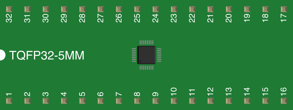
 Design with TVP5150 in Cirkit Designer
Introduction
The TVP5150AM1 is a high-performance video decoder manufactured by Texas Instruments. It is designed to convert analog video signals into digital formats, supporting a wide range of video standards such as NTSC, PAL, and SECAM. The TVP5150 is widely used in applications like video surveillance systems, video conferencing equipment, multimedia devices, and set-top boxes. Its compact design and low power consumption make it an ideal choice for embedded systems requiring video decoding functionality.
Explore Projects Built with TVP5150
 Open Project in Cirkit Designer
 Open Project in Cirkit Designer
 Open Project in Cirkit Designer
 Open Project in Cirkit Designer
Explore Projects Built with TVP5150
Open Project in Cirkit DesignerOpen Project in Cirkit DesignerOpen Project in Cirkit DesignerOpen Project in Cirkit DesignerTechnical Specifications
The following are the key technical details of the TVP5150AM1:
- Input Video Standards: NTSC, PAL, SECAM
- Output Format: 8-bit ITU-R BT.656 digital video
- Input Signal Types: Composite video (CVBS), S-Video (Y/C)
- Supply Voltage: 3.3V (typical)
- Power Consumption: 113 mW (typical)
- Operating Temperature Range: -40°C to 85°C
- I2C Interface: Supports communication with host processors
- Integrated Features:
- Adaptive 4-line comb filter for NTSC/PAL
- Automatic gain control (AGC)
- Color killer for noisy signals
- Macrovision detection
Pin Configuration and Descriptions
The TVP5150AM1 is available in a 32-pin TQFP package. Below is the pin configuration and description:
| Pin Number | Pin Name | Type | Description |
|---|---|---|---|
| 1 | AVDD | Power | Analog power supply (3.3V). |
| 2 | AGND | Ground | Analog ground. |
| 3 | CVBS/YIN | Input | Composite video or luminance input. |
| 4 | CIN | Input | Chrominance input for S-Video. |
| 5 | RESETB | Input | Active-low reset pin. |
| 6 | SDA | Input/Output | I2C data line. |
| 7 | SCL | Input | I2C clock line. |
| 8 | DGND | Ground | Digital ground. |
| 9 | DVDD | Power | Digital power supply (3.3V). |
| 10 | PCLK | Output | Pixel clock output. |
| 11 | VSYNC | Output | Vertical sync signal output. |
| 12 | HSYNC | Output | Horizontal sync signal output. |
| 13-20 | D0-D7 | Output | 8-bit digital video data output. |
| 21 | XTAL1 | Input | Crystal oscillator input or external clock input. |
| 22 | XTAL2 | Output | Crystal oscillator output. |
| 23 | TEST1 | Input | Test pin (must be tied to ground in normal operation). |
| 24 | TEST2 | Input | Test pin (must be tied to ground in normal operation). |
| 25 | TEST3 | Input | Test pin (must be tied to ground in normal operation). |
| 26 | TEST4 | Input | Test pin (must be tied to ground in normal operation). |
| 27 | AGND | Ground | Analog ground. |
| 28 | AVDD | Power | Analog power supply (3.3V). |
| 29 | YOUT | Output | Luminance output for S-Video. |
| 30 | COUT | Output | Chrominance output for S-Video. |
| 31 | DGND | Ground | Digital ground. |
| 32 | DVDD | Power | Digital power supply (3.3V). |
Usage Instructions
How to Use the TVP5150 in a Circuit
- Power Supply: Connect the analog (AVDD) and digital (DVDD) power pins to a stable 3.3V power source. Ensure proper decoupling capacitors are placed close to the power pins to minimize noise.
- Video Input: Connect the composite video signal to the CVBS/YIN pin. For S-Video, connect the luminance signal to CVBS/YIN and the chrominance signal to CIN.
- Clock Source: Provide a 27 MHz clock signal to the XTAL1 pin, either through a crystal oscillator or an external clock generator.
- I2C Communication: Use the SDA and SCL pins to configure the TVP5150 via the I2C interface. The default I2C address is
0xB8for write operations and0xB9for read operations. - Digital Output: Connect the D0-D7 pins to the digital video input of a microcontroller, FPGA, or video processor. Use the PCLK, VSYNC, and HSYNC signals for synchronization.
Important Considerations and Best Practices
- Signal Integrity: Use proper shielding and grounding techniques to minimize noise in the analog video signals.
- Reset: Ensure the RESETB pin is held low during power-up to initialize the device properly.
- Termination Resistors: Use 75-ohm termination resistors for the video input signals to match the impedance of the video source.
- I2C Configuration: Configure the TVP5150 registers via I2C to select the desired video standard and output format.
Example: Connecting TVP5150 to Arduino UNO
Below is an example of how to interface the TVP5150 with an Arduino UNO using the I2C interface:
#include <Wire.h> // Include the Wire library for I2C communication

#define TVP5150_I2C_ADDRESS 0xB8 // TVP5150 I2C address for write operations

void setup() {
  Wire.begin(); // Initialize I2C communication
  Serial.begin(9600); // Initialize serial communication for debugging

  // Reset the TVP5150
  pinMode(7, OUTPUT); // Assume RESETB is connected to Arduino pin 7
  digitalWrite(7, LOW); // Hold RESETB low
  delay(10); // Wait for 10ms
  digitalWrite(7, HIGH); // Release RESETB

  // Configure TVP5150 via I2C
  Wire.beginTransmission(TVP5150_I2C_ADDRESS >> 1); // Start I2C transmission
  Wire.write(0x00); // Write to register 0x00 (example register)
  Wire.write(0x01); // Example value to configure the register
  Wire.endTransmission(); // End I2C transmission

  Serial.println("TVP5150 initialized.");
}

void loop() {
  // Add code to process video data or monitor TVP5150 status
}
Troubleshooting and FAQs
Common Issues
No Video Output:
- Ensure the video input signals are properly connected and terminated with 75-ohm resistors.
- Verify that the TVP5150 is configured correctly via I2C.
- Check the power supply and ensure the device is receiving 3.3V.
I2C Communication Failure:
- Confirm the I2C pull-up resistors (typically 4.7k ohms) are present on the SDA and SCL lines.
- Verify the I2C address being used matches the TVP5150's address.
Synchronization Issues:
- Ensure the PCLK, VSYNC, and HSYNC signals are properly connected to the receiving device.
- Verify the clock source (XTAL1) is stable and operating at 27 MHz.
FAQs
Q: Can the TVP5150 decode HD video signals?
A: No, the TVP5150 is designed for standard-definition (SD) video signals such as NTSC, PAL, and SECAM.
Q: What is the default output format of the TVP5150?
A: The default output format is 8-bit ITU-R BT.656 digital video.
Q: Can the TVP5150 operate without an I2C host?
A: Yes, the TVP5150 can operate in a default mode without I2C configuration, but advanced features require I2C programming.
Q: How do I detect Macrovision-protected content?
A: The TVP5150 includes Macrovision detection functionality, which can be accessed via specific I2C registers. Refer to the datasheet for details.