How to Use BC337 Top: Examples, Pinouts, and Specs
Introduction
The BC337 is an NPN bipolar junction transistor (BJT) designed for general-purpose amplification and switching applications. It is widely used in low to medium power circuits due to its ability to handle a maximum collector current of 800 mA and a voltage rating of 45 V. Its compact size and versatility make it a popular choice for hobbyists and professionals alike.
Explore Projects Built with BC337 Top


Explore Projects Built with BC337 Top
Common Applications
- Signal amplification in audio and RF circuits
- Low-power switching applications
- Driving small loads such as LEDs, relays, or small motors
- Used in Darlington pair configurations for higher current gain
- General-purpose electronic projects and prototyping
Technical Specifications
Below are the key technical details of the BC337 transistor:
| Parameter | Value |
|---|---|
| Transistor Type | NPN |
| Maximum Collector Current (Ic) | 800 mA |
| Maximum Collector-Emitter Voltage (Vce) | 45 V |
| Maximum Collector-Base Voltage (Vcb) | 50 V |
| Maximum Emitter-Base Voltage (Veb) | 5 V |
| DC Current Gain (hFE) | 100 to 630 (varies by model) |
| Power Dissipation (Ptot) | 625 mW |
| Transition Frequency (ft) | 100 MHz |
| Package Type | TO-92 |
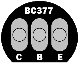
Pin Configuration
The BC337 transistor comes in a TO-92 package with three pins. The pinout is as follows:
| Pin Number | Pin Name | Description |
|---|---|---|
| 1 | Collector | Current flows into this pin |
| 2 | Base | Controls the transistor's operation |
| 3 | Emitter | Current flows out of this pin |
Below is a diagram of the BC337 pin configuration (viewed from the flat side of the TO-92 package):
   _______
  |       |
  |       |
  |_______|
   | | |
   1 2 3
   C B E
Usage Instructions
Using the BC337 in a Circuit
The BC337 transistor can be used as a switch or an amplifier. Below are the steps to use it in a circuit:
Determine the Operating Mode:
- Switching Mode: Use the transistor to control a load (e.g., LED, motor) by applying a small current to the base.
- Amplification Mode: Use the transistor to amplify a small input signal.
Base Resistor Calculation:
- To protect the transistor, calculate the base resistor value using the formula:
[
R_b = \frac{V_{in} - V_{be}}{I_b}
]
Where:
- ( V_{in} ) is the input voltage to the base.
- ( V_{be} ) is the base-emitter voltage (typically 0.7 V for the BC337).
- ( I_b ) is the base current, which can be approximated as ( I_c / h_{FE} ).
- To protect the transistor, calculate the base resistor value using the formula:
[
R_b = \frac{V_{in} - V_{be}}{I_b}
]
Where:
Connect the Circuit:
- Connect the collector to the positive side of the load.
- Connect the emitter to ground.
- Use a base resistor to connect the base to the control signal.
Example: Controlling an LED with Arduino UNO
Below is an example of using the BC337 to control an LED with an Arduino UNO:
Circuit Diagram
- Collector: Connect to the positive terminal of the LED (with a current-limiting resistor in series).
- Emitter: Connect to ground.
- Base: Connect to an Arduino digital pin through a 1 kΩ resistor.
Arduino Code
// Define the pin connected to the BC337 base
const int transistorPin = 9; // Digital pin 9

void setup() {
  pinMode(transistorPin, OUTPUT); // Set the pin as an output
}

void loop() {
  digitalWrite(transistorPin, HIGH); // Turn on the LED
  delay(1000); // Wait for 1 second
  digitalWrite(transistorPin, LOW);  // Turn off the LED
  delay(1000); // Wait for 1 second
}
Important Considerations
- Heat Dissipation: Ensure the transistor does not exceed its maximum power dissipation of 625 mW. Use a heatsink if necessary.
- Voltage Ratings: Do not exceed the maximum voltage ratings (e.g., 45 V for Vce).
- Current Ratings: Ensure the load does not draw more than 800 mA through the collector.
Troubleshooting and FAQs
Common Issues
Transistor Overheating:
- Cause: Exceeding the maximum power dissipation or current rating.
- Solution: Use a heatsink or reduce the load current.
No Output Signal:
- Cause: Incorrect base resistor value or insufficient base current.
- Solution: Recalculate the base resistor value and ensure the base current is sufficient.
Load Not Turning Off:
- Cause: Leakage current or improper wiring.
- Solution: Check the wiring and ensure the base is properly grounded when the transistor is off.
Damaged Transistor:
- Cause: Exceeding voltage or current ratings.
- Solution: Replace the transistor and ensure the circuit operates within safe limits.
FAQs
Q1: Can the BC337 be used for high-power applications?
A1: No, the BC337 is designed for low to medium power applications. For high-power applications, consider using power transistors like the TIP120.
Q2: What is the difference between the BC337 and BC547?
A2: The BC337 can handle higher currents (up to 800 mA) compared to the BC547 (100 mA), making it more suitable for driving larger loads.
Q3: Can I use the BC337 in a Darlington pair?
A3: Yes, the BC337 can be used in a Darlington pair configuration to achieve higher current gain.
Q4: What is the maximum frequency the BC337 can handle?
A4: The BC337 has a transition frequency (( f_t )) of 100 MHz, making it suitable for low-frequency applications.